3-Wire Transmitter Analogue Wiring

jspann7

Member
Join Date
May 2011
Location
Rockhampton, Australia
Posts
19
Hi Guys,

I have been looking around for an answer to my question and so far have had no success.

I have an AB 1762-OF4 module which is connected to a ML 1400 1766-L32BWA PLC. I need to run a proportional solenoid valve with the 4-20mA output of the module however I am stuck.

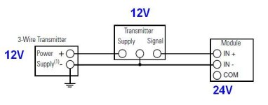
The solenoid is 12V DC but the 1762-OF4 is 24 DC. The solenoid is wired via a 3-wire transmitter - the power supply for the setup shares the common of the transmitter with the common of the analogue output. I know the analogue card doesn't output any power, it's merely a 4-20 mA signal.

I need to how I can get this to work considering I have two different voltage ratings for the transmitter and the analogue module.

My electrician originally asked me this question. I attached a diagram of the setup.

Also, if my question seems naive, it's because I'm actually a mechanical engineer.
icon12.gif


Thanks in advance.

3-Wire Transmitter.jpg
 
You can't wire a transmitter to an output card. They are both trying to control the loop.

Or am I missing something here. What is this transmitter?
 
Mickey,

I think that in the drawing, the 12 volt DC proportional solenoid is mislabeled "3-Wire Transmitter".

Edit: No wait, that will not make sense either. Something is wrong or missing, or this was done by a mechanical hack!

JS, What you posted is the standard wiring diagram for how to wire a 3-wire signal transmitter with it's own external power supply to a MicroLogix PLC Analog INPUT. But you said your proportional solenoid is wired to a 1762-OF4 Analog OUTPUT module. The twain ard different and shall never mix or work if you wire Outputs like a diagram made for INPUTS.

More information needed. What the heck is really going on? As Earthscape said' "Do you have the make and model of the solenoid"?
 
Last edited:
Mickey,

Even if the transmitter is mislabeled, still the box on the right is plainly an analog input module, therefore will not serve as an OUTPUT to control a solenoid valve, proportional or otherwise.

Those poor mechanical engineers always get into trouble when they get away from air conditioning systems....;)

Maybe the solenoid has an analog input that tells it how far to open, and an analog ouput that sends its position back to the PLC? Nah, that is way too complicated, right?
 
Last edited:
OK. Sorry for any confusion.

The proportional solenoid is:
Make: Command Controls Corp.
Model: EPFD-16-N-10-0-M-12DG

To function with the analogue output of the module it needs:

Make: Command Controls Corp.
Model: PWM-1400-12

This is the 'transmitter' I'm talking about.

Refer to the attached.

The solenoid is connected to terminals 6 and 7, the 12V DC power supply is connected to terminals 4 and 5, the analogue +ve output (4-20mA current) is connected to terminal 1 and the common is connected to terminal 4. This matches the '3-wire transmitter' setup I was talking about.

Thanks for your replies so far.

Joel
 
Mickey,

Even if the transmitter is mislabeled, still the box on the right is plainly an analog input module, therefore will not serve as an OUTPUT to control a solenoid valve, proportional or otherwise.

Those poor mechanical engineers always get into trouble when they get away from air conditioning systems....;)

Maybe the solenoid has an analog input that tells it how far to open, and an analog ouput that sends its position back to the PLC? Nah, that is way too complicated, right?


You are making me queasy.
 
Last edited:
My read is the output from your PLC ( 4-20ma) (0-20ma) would connect to terminals 1 and 3 only.
2 and 3 for voltage. No connection to the power common.

The drawing shows the pot connected to the power common only to power the pot.

You may want to consider an isolator between the PLC output and the Valve controller.
 
Last edited:
See picture.

Your solenoid must have its own 12 volt power supply, which has nothing to do with the analog control signal coming out of the 1662-OF4.

Look at the wiring diagram for the solenoid. Your analog current signal from the PLC should be connected to terminals 1 (+) and 3 (-).

Proportional Solenoid Current Input Signal.jpg
 
Last edited:
Lancie1,

Thanks. Just to make sure I;ve got this:

1 = Analog Out +ve
2 = n/a
3 = Analog Out -ve (com)
4 = 12V DC -ve
5 = 12V DC +ve
6 & 7 are the coil.

If thats right then thank you to everyone for your help!

Joel
 
Yes, that is the correct wiring. Now as Mickey said, the 1762-OF4 module cannot be configured for either 1-5 volts or 0-20 mA (many other Allen Bradley modules can be). Therefore you do need some type of signal converter to convert the 4-20 mA signal to 0-20 mA. You may have one already. That "transmitter" you mentioned sounds like it might be a signal converter. If not, then you can buy one from many different vendors that will do the job. That is probably the best way overall to make this thing work.

Phoenix Contact is one brand of signal converter (also called signal isolator). You need one that takes a 0-20 mA input and converts it to a 4-20 mA output (which then is wired to your Commnad Controls solenoid). Notice that most of these converters will need their own power supply, so I would look at where it will be mounted, and if near the PLC, look for a 24 VDC converter, but if located at the solenoid, then try to find one that runs on 12 VDC.

http://www.phoenixcontact.com/signal-level-matching/31244_14827.htm
 
Last edited:
I went back and took a closer look at the 1762-OF4's manual and it can be configured for 0-20ma see pdf below. I edited my post to delete that info about it's output ranges. Sorry for any confusion. Still a little queasy.
 
I just realised that I have the 1762-IF2OF2 module, not the OF4 module...

The IF2OF2 has an analog normal operating range (Current) 4 to 20 mA and a full scalar analog range of 0 to 21 mA. Can this module be configured to 0-20mA, and if so, how?

Thanks,
 

Similar Topics

Hello, I have a simple 3-wire 4-20mA pressure transmitter which I would like to split into two signals to send one to the devices interface and...
Replies
7
Views
3,632
Does anyone have experience wiring this type of analog pressure transmitter up? It's 4 wires. 3 blacks and 1 green which I assume is earth...
Replies
9
Views
269
I have read a lot about this. One of what I saw is 4 wire is used when the voltage drop is high because of wire and transmitter itself but I don't...
Replies
4
Views
2,477
Hi, Calculation of voltage drop of a 2 wire transmitter connected to plc AI is pretty simple and straight forward. My Question is could you...
Replies
4
Views
2,144
how to connect three number 4 wire transmitter to analog card IF16 1756 plc
Replies
7
Views
3,268
Back
Top Bottom