3-Wire Transmitter Analogue Wiring

Hi Jspann7,

The way I read it is that the valve is setup for 0-12V proportional control via PWM.
The Amplifier (PWM-1400-12) can take in a supply from 9 to 32V (Normal range for mobile applications) and will output the correct voltage for the valve. Therefore, it is probably OK to connect the PLC card and amplifier card to the same 24VDC supply. As also mentioned, the proportional valve coil should only be connected across the 6 and 7 terminals of the amplifier, and must not be directly connected to either the positive or negative (0VDC) terminal of the DC power supply.
Finally, I would check this with whoever sold you the unit.

As for the PLC output, it is programmable to give you 0-20mA. You can put out 21mA from it, and a small number of devices can use this extra current to compensate for devices built with wide tolerances.

Hope this helps,

Doug
 
Thanks for the reply Doug,

Just a quick note, the power supply is 12V DC as the solenoid is 12V DC. Does this create a problem?

I'm searching for how to program it to 0-20mA at the moment; it's configured for 4-20mA and I can scale the output (SCP) so that 4mA = 0% and 20mA = 100% but I'm afraid this isn't what I am trying to achieve.

Joel
 
OK, the output card you are using will send current from the output, through the device, then back to the "Common" or 0VDC. So, as long as the 12VDC supply 0 V is connected to the 0V of the PLC output card, and the 12VDC part of that supply is kept away from any PLC connection, you should be OK. So, 12VDC supply, +12V connected to amplifier terminal 5. 12VDC power supply 0VDC connected to amplifier terminal 4, and PLC card terminal COM.
PLC I out 0 terminal to be connected to amplifier terminal 1.
Proportional valve connected across amplifier terminals 6 and 7.

Should work if I read everything right.
 
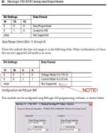
The data format I posted in post #14 should also work for this card 1762-IF2OF2.

See Knowledgebase article
18075 - 1762-IF2OF2 Input/Output Data Formats/Conversion Times

It needs a "Tech Connect" to view though. I don't have one. Those that do can double check it.
 
Last edited:
Hmmm...

Mickey, I donloaded the 1762-OF4 Installation Manual from Ab.com, and it shows that OF4 can only be software-configured for 0-10 Volts or 4-20mA. Apparently at some point there was a change made in this module. The question now is "which one does Joel have"?

I just realised that I have the 1762-IF2OF2 module, not the OF4 module...
Oh, wait, he doesn't have either! Now I am getting quesy! Who knows?

Here is Page 22 from the 1762-IF2OF2 Analog Input/Output Module Installation Manual (dated April 2011), Configuration Data File beginning on Page 21. It shows only 0-10 volts or 4-20 mA as programmable options.

I think you need a signal converter or signal isolator to rescale this output to 0-20 mA. Wire your 4-20 mA signal from the analog module to the Input terminals on the converter, and wire the converter Output terminals to your Solenoid terminals 1 and 3. Also connect DC power to the converter (24 VDC most likely).

1762-IF2OF2 Congifuration.jpg
 
Last edited:
@ Lancie1 & Doug Adam:
You both have different ideas of how to wire the outputs of the module up; 1 & 3, 1 & 4. I have to wire the output to the load on the valve driver, I know it has to be PLC [I Out(+)] to 1, but is PLC [COM] to 3 or 4?

Regards.
 
Hi Joel,

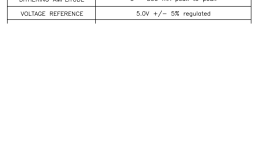
The amplifier module terminal 3 is a reference voltage of 5V. This is to allow a potentiometer to be connected ( as per the diagram) for output control. You must connect the PLC COM to terminal 4.

As for the other issue of the PLC only giving 4-20mA, I would just test this on the bench. Use a 100 ohm resistor to simulate the output module before connection. Be ready to get a converter if needed.

I have to admit, every analog output I have done with one of these AB PLC modules was on 4-20 mA and never 0-20mA.

I stand corrected. See picture.

voltageRef.PNG
 
The amplifier module terminal 3 is a reference voltage of 5V. This is to allow a potentiometer to be connected ( as per the diagram) for output control. You must connect the PLC COM to terminal 4.
Well, hmmm. Getting queasier.

Let's do it line by line. Now accoring to the Sheet 11-002 by Command Controls Controls Corp, Terminal 4 is "Power" and an input from "- DC Power Supply" is shown going to terminal 4, so that means Terminal 4 = -12 Volts DC, and Terminal 5 is + 12 Volts DC. Everbody agree with this so far?

Now we look at the optional 10K external Potentiomenter circuit. One leg of the pot connects to "- DC Power Supply", which we have all agreed is going to be -12 volts DC. Coming out the center wiper is going to be what? We know from the specs that the maximum voltage to Terminal 2 "Volts" is 5 volts, because the voltage control range (shown on Page 11-002.1) is "0 to 5 Volts". Therefore, by induction, Terminal 3 Reference voltage will be 5 volts (12 volts reduced through the 10k pot resistance), and current = 5 mA.

BUT THAT IS ONLY IF THE POT IS CONNECTED. Without the pot, Terminal 3 should be 0 volts. Wait, isn't that what we want for our "- 0 mA" leg coming from the analog output module? On the other hand, do we want to pass the foreign -12 VDC (technically 0 volts I suppose if it is grounded) through the analog output module and then back to the PWM-100-12?
 
Last edited:
Hi Lancie,

I disagree, I read terminals 4 and 5 as the input voltage of 9 to 32VDC, with Joel connecting 12VDC. The positive side of this will be 12VDC, while the negative will be 0VDC. I have assumed the normal method of earthing the 0V side of the supply. There should be no -12VDC, and I believe that a split supply is not being used.
 
Yeah, yeah. I was referring to the drawing supplied by the manufacturer. See that little "Power -" there next to Terminal 4? If they want to call it "Power -" that is okay with me. Why quibble?
 
This discussion about which terminal to connect to is another good reason to install an isolator as I and Lancie1 have mentioned.

I don't like connecting the commons of two different sources together. I also don't like to ground DC power commons (ground is a very noisy environment).
 
Last edited:

Similar Topics

Hello, I have a simple 3-wire 4-20mA pressure transmitter which I would like to split into two signals to send one to the devices interface and...
Replies
7
Views
3,635
Does anyone have experience wiring this type of analog pressure transmitter up? It's 4 wires. 3 blacks and 1 green which I assume is earth...
Replies
9
Views
269
I have read a lot about this. One of what I saw is 4 wire is used when the voltage drop is high because of wire and transmitter itself but I don't...
Replies
4
Views
2,477
Hi, Calculation of voltage drop of a 2 wire transmitter connected to plc AI is pretty simple and straight forward. My Question is could you...
Replies
4
Views
2,144
how to connect three number 4 wire transmitter to analog card IF16 1756 plc
Replies
7
Views
3,268
Back
Top Bottom