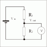
Hello everyone, I am using 1762-IF4 module and i want to test it by supplying 0-10V variable supply. I am using 24VDC supply, then how could i make this 24VDC supply to work as 0-10VDC variable supply ? What would be the Value of POT that i need to use ?
Analog module testing
- Thread starter gibson
- Start date
Similar Topics
Good afternoon, I am currently working with an HMI/PLC LP-a070 and I require at least one analog output, but the PLC does not have one. I was...
Why AMIo800 Analog input module's I/O LED is Lighting up Red?
Checked module connections, 4-20ma wires etc but this light is continuously Lighting...
In this sample programming, what does U4 mean?
Any assistance would be greatly appreciated.
I have run into a problem with my first time installing a 2080-OF2 module on a Micro820 and have a hunch that the module itself - brand new out of...
Good morning Guys,
PLC: micrologic 1500 LRP 24bwa c series
soft: Rslogix 500
We are required to consider the weight of the product in such a way...


