Beginner with encoders help!

dp96

Member
Join Date
Sep 2023
Location
georgia
Posts
22
First time poster here

so long story short i built my own trainer at work so i could toy around with various things and test things and learn. well today i started with learning motion logic in studio5000. I have a M02AE card and a sew eurodrive TTL encoder(incremental). well i tried putting a BEI sensor card that lights up with A B and Z positions so that i could accurately tell when im getting phases and so on. my issue is i power the encoder and BEI card with 24v DC. off the encoder usually whatever phase is active im showing around 3-4v and the innactive phase will be around 1 so if A+ is 3.5 hen A- is 1 and so on. if i spin the encoder i can see the voltages change with position. my issue is on the BEI card i wired the controller side part to go back to the PLC. well none of the voltages fluctuate and none of the BEI cards lights go off. i noticed all the negative phases on the plc side of the bei card stay at 4 volts and the positives 0 and it does not change even when the topside of the card(encoder outputs) are fluctuating.

Now if i hook the wires from encoder straight to the m02ae card i can see in the plc that it is showing position and i can rotate it and itll change. My problem is im not sastified with that. i really want to know why the bei card in the middle is causing the plc to not see position so i can understand more.

Any help will be gladly appreciated!!!

encoder- OG72-DN-1024-R (i believe im not looking at it right now) ES1R model
1756-M02AE A rev 30
BEI Sensor module 600001-012 (same as encoder not 100 percent but its the 25 in/5 out module
 
To me it sounds like the BEI voltage is somehow powering up the PLC TTL inputs.


It may be the internal handling of the A,B,Z signals on the 2 components trying to read them together is causing a short circuit.


You may not be able to have the BEI card connected with the PLC.


I'm guessing as I've seen other weird things happen, so maybe someone else here can provide more info.
 
any possibility that jumping off the power and 0v of the bei card to feed the encoder is messing with it?. Its just so weird because we use other brands of encoders with this same bei card and m02ae all over work i wouldnt figure itd be that much different unless they arent ttl signal encoders?

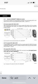
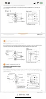
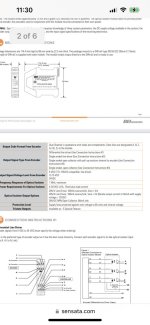
i did read that there were 3 ways to wire single ended, open source, and differential line, but i have zero clue on how to tell which this specific encoder is

ill have to experiment more sunday

ill post pictures of the diagrams im looking at tho the sew eurodrive diagram wont help much

also the terminals inside the encpder are Power common A B C A- B- C- then the last two say sensor power and common which are always the same voltage as whatever i put on mian power terminals. i have no clue what they are for but the manual says not needed at 24v?

IMG_4285.jpg IMG_4286.jpg IMG_4288.jpg IMG_4289.jpg
 
my bad I am basically using the encoder for just feedback for testing the drive isnt connected in this situation so its basically the encoder is connected to the bei and the other side of vei card goes back to plc rack on the m02ae card. i have 24 volts feeding the bei card and i jumped off the bei card power to feed encoder 24volts
 
the bei card(or module i should say) isnt on the plc rack it is basically just a middle man that lets you see A B Z light up as you spin the encoder so you can see exactly what point you are on. i can just bypass this and hook encoder straight to plc but was just curious why this bei optical module is messing with things when its just supposed to allow the phases from encoder to pass through to plc while showing you the phases in action
 
here is a picture of bei the encoder wites hook to encoder side and controller side is where you hook the wires coming from m02ae its supposed to match A to A B to B etc

IMG_4293.jpg
 
nevermind it hit me like a brick looking at it this morning this ttl encoder only outputs 3.5 volts cause 1.5 is on the not phases at all times when an plus phase is made( so high and low signals) and i believe the bei card needs 5 volts on inputs not sure if i can change the encoder to put out full 5 volts or not
 
nevermind it hit me like a brick looking at it this morning this ttl encoder only outputs 3.5 volts cause 1.5 is on the not phases at all times when an plus phase is made( so high and low signals) and i believe the bei card needs 5 volts on inputs not sure if i can change the encoder to put out full 5 volts or not


Someone with electronics experience could build a 5V powered interface circuit board that used the 3.5v to trigger fast enough transistors that output 5V for the BEI card to use.


But in that case it would be simpler to drop the BEI card and have that interface read the encoder in series with the PLC and light its own LED's


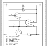
My thought on that would be something like the Twin-T (twin transistors) detection circuit used on model railroads to detect current in either direction in a block, but since the encoder would always be putting out the same polarity it would only need one way detection

Capture.PNG
 
hey thanks i ended up looking around work and found another bei module that looked exactly the same but pnly difference is it also excepted 3volt inputs and boom worked like a charm but i do have circuit boards and transistors so i definitely will experiment with what you showed me only question is with this high and low signal encoder it put out voltage on both A and Anot B and bNot etc whenever A, B, or Z is made would your example still work in that case. for instanc einstea dof straight 5v when A is made and A not at 0v this encoder instead has 3.5v on A made and 1.5 on Anot?
 
From my use and understanding of this circuit when I did model railroading (back in the 80's) that circuit would be wired on A+, 2 similar circuits on B+ and Z+ if you want them, but A would cycle enough for you to know the encoder was moving.


Since the diodes are there to drop a potential 18 volts to 1.5 to trigger the transistors you wouldn't need them at all. You could run the encoders 3.5 volts directly through the transistor. Also since the A+ signal will always be positive you won't need the second, reversed transistor.


Then, as this was designed to trip a relay, the 12V power could be reduced to 3.5 or 5V as you only want to light a LED. If you had 3 of these for A, B & Z then a single 3.5 volt power source could be used for all 3, as the model railroads could have 100 of these all running off a single 12V source.
 
okay i think i grasp it the bei card does have a way of wiring all the not phases(A- B- C-) to common so i could have the other phases trigger the relay and thus being able to read all three phases if im understanding correctly?

also i would assume i dont need the capacitor in the diagram as i could just have 24 volts wired to the control realy as the bei card accepts 5-28 volt inputs and just have the 3.5 volts switch the relay?
 
or is the capacitor needed to pull in the relay and the 3.5 volts is there to keep it held after the capacitor has full charged and switched off?
 
For your application a relay wouldn't work. The relay doesn't act as a motion detector, or pulse detector. It will be on whenever the A signal (or B or Z) is on. If the encoder stopped with the A signal on the relay would stay on.


If you are using a relay out on the BEI card to detect motion then this detector won't do that.


The capacitor is probably needed to stop the 12V in the example from powering the railroad track, or going back through the rails and triggering another detector. Guessing here, but the original was all DC, no AC, and the capacitor was needed.
 
i may be confused here but the encoder only puts 3.5 volts on A or any other phase when its made any other time the phases are at 0 volts so wouldnt the relay only come on when a phase is made and thus showing motion? so when A is made 3.5 volts would trigger a relay and send 24voltbpower to bei card which sees 24 volt input and outputs 5 volts to the plc to be read as A+ on then go off when A goes to 0v B phase would go to 3.5 volts and trigger another relay and then drop to 0v and so on
 

Similar Topics

Hi all, Writng a FB in ST on Beckhoff TC for a pulser which turns on and off on a cycle, is paused by turning bControlInput to FALSE, but resumes...
Replies
6
Views
251
So to start off: I have no experience with PLC's, but I'm good at figuring stuff out, but I need some help to know if my PLC is just dead in the...
Replies
2
Views
115
Dear all, First of all thanks for letting me join this forum. I just need some help in one of my programming exercises. Being a beginner...
Replies
6
Views
611
I am trying to connect to SLC5/03 using an FTDI usb to rs232 with female to female converter at 1 end... however I can not connect to it ... the...
Replies
8
Views
1,270
So I work for a company that doesn’t allow code change without going through a lot of people. Anyway my question is I have a sensor and when it...
Replies
12
Views
1,793
Back
Top Bottom