Conveyor Belt

Since you've been given no data on the robot performance, I would assume that it can handle what is fed to it.
I always dreamed of inventing a machine with variable and infinite capacity. Think of what a price I could get! Now someone has beat me to it with a lousy robot that runs at the speed of light.
 
Last edited:
Looking at the schematic again, I see no sensor or photoeye that could prevent a build-up at the palletiser robot end...

I'll stand my ground and say that this exercise is about relative conveyor speeds...
 
First, thank you everyone for the help you have all posted! Im finding I starting to understand PLCs a lot more by browsing the forum, vice looking in my text book.

So i have started my ladder logic program, but have run into a couple snags. I want to program a dis-enable/ enable function with the labeler that helps ensure the label will be applied correctly. For that should I use a timer that controls a bit in the conveyor run rung? The route I was thinking was have the timer energize a XIO contact and then de-energize it when it is done timing. Also, how could I prevent the labeler from continously applying a label if the conveyor is stopped for another reason and a case is present at the labeler photoeye?
 
For that should I use a timer that controls a bit in the conveyor run rung?
See RET's Post #11 in this thread, step 3. Use Step relays or step values to control which step your process is in, the when the previous step is done, go to the next step. For the labeler case, when Step 2 is done (Case present at labeler and Conveyor #2 stopped, then go do Step 3 (Apply label).

Timers are the least desirable method because just because some time has passed does not mean your label was applied. You really need feedback signals from your machine to tell the PLC what is going on (sensors that say things such as Label applied (or not applied), Conveyor running (or not running), and so on. This type of feedback makes your system smarter and more reliable. Otherwise it is fat, dumb, and unhappy.

The system in the picture only has 3 feedback sensor, the 3 photoeyes. A real setup would probably have many more. For example, the labeler probably would need some type of detector that looked to see if the label was actually stuck in place. If not, there should be an alarm, and maybe a halt until the labeler was fixed (maybe it just run out of label material).
 
Last edited:
Use Step relays or step values to control which step your process is in, the when the previous step is done, go to the next step.


How would I program something like that in? I havent learned it and the book doesnt have it in it.
 
Also, how could I prevent the labeler from continously applying a label if the conveyor is stopped for another reason and a case is present at the labeler photoeye?
Turn on the Labeler output using a one-shot instruction. Each time your logic calls for it to go ON, it will only go on one time, until the rung logic goes false again.
 
How would I program something like that in? I havent learned it and the book doesnt have it in it.
After writing a trial program using the LogixPro simulator software, you don't really need any step relays or sequencer-type instructions. I used 4 timers, 3 outputs, and the 5 inputs.
 
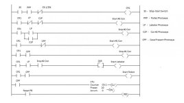
Here is what I have created so far, but I am stuck on a couple things.
- Restart #2 Conveyor after label applied (Im thinking a timer, but still havent worked out how exactly it would be programmed in)
- Having Conveyor #2 started if no case is at case present photoeye (Not sure how to override the fact that Conveyor #2 is stopped when it reaches the #2 Con photoeye)

plc.jpg
 
Restart #2 Conveyor after label applied (Im thinking a timer, but still havent worked out how exactly it would be programmed in).
I found the robot cycle time, and used that to set the spacing timer. If you want to keep it simple, just set a time for your Spacing Timer (make a guess) and make a trial run.

(Not sure how to override the fact that Conveyor #2 is stopped when it reaches the #2 Con photoeye)
That is the heart of the problem, and why they mentioned "spacing". What you do is use a timer that starts when the #2 Conveyor Photoeye is first triggered AND Conveyor #1 is running. This timer runs for x seconds (this is where you make a guess if you don't know how long it takes the robot to cycle). Say you pick 2 seconds for Spacing Timer 1. It gets triggered by the photoeye, seals itself ON so that it keeps running until done. When this Spacing Timer 1 is done, you then use that to start Conveyor #2, moving the case at the end onto Conveyor#1 (which has already been running for 2 seconds and will develop a 2 second gap now at the front, ready for the next case.

If the robot takes longer than 2 seconds to stack a case, then cases will pile up at the end of Conveyor 1. Then you increase the Preset time for the Spacing Timer until the robot speed averages the same as your spacing time gap. On the other hand, if the Spacing Timer is too long, the robot will be waiting for the next case. Idealy you want the case to arrive at the end of Conveyor 1 just as the robot swings back for the next pickup. The ideal is rarely achieved in the real world.

I will enter your program into LogixPro and see how it runs.
 
Last edited:
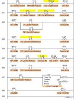
Here is your program in LogixPro. There are several problems, but one at a time. Now I AssUMe that this program has to be capable of actually running on the lab-type setup for this packaging system that I have seen used by other students - in other words, use real-world conditions and times for things to happen.

It starts okay, but quits at Rung 2. When the LP- Labeler Photoeye goes ON, Conveyor 2 Stops. Now there is nothing to restart it again (remember that the photoeye is still ON and still seeing the case under the labeler). You need a timer that is triggered by the "Start Labeler" bit on Rung 005, then waits a short period (say 1/2 second) for the label to be attached, then with its DN bit, starts a second timer that runs Conveyor 2 until the case has time to clear the Labeler Photoeye.

Rungs 001-002 and 003-004 for the Conveyor Outputs: You can condense these into 2 rungs, a Conveyor RUN output for each one. That is the common good way to do motor outputs. You don't want to get into the habit of using Start and Stop bits. Combine your Start and Stop logic into one rung. For Rungs 3 and 4, it is simple: Use an OTE (Output Energize) on Rung 003, and delete Rung 004 - you don't need it.

Rung 005: You have a one shot bit to trigger the Labeler, but no output for it. The Labeler Output really needs to stay on longer than 1 PLC scan, so use a timer here to keep a Labeler Output ON for at least 0.5 seconds (long enough that you can see that it goes ON. With a one-shot, it happens so fast you will never see it, and the physical labeler machine may not see it either.

Rung 006: You have an Output to start the robot, but the original problem layout does not show any control that you have of the robot. In other words, you do not necessarily have a PLC Output for the robot. I would delete this one.

Rung 007: Your counter will count up to 20 cases then stop the system. That works okay, but is it what was specified? In other words, are you using this counter because the "customer" said he wanted a counter that counted 20 cases, then stopped? I don't think so. You did it because you liked it. That can get you in trouble and may get some points knocked off your grade.

What was mentioned was "spacing" of the cases. You don't have a way to do that - yet. We will get there eventually. Set up a Spacing Timer set for 2 seconds that keeps Conveyor 2 from running until Conveyor 1 has run 2 seconds. (Maybe it is a slow system and you should use 4 seconds - we don't know without a timer that would measure the robot cycle and use the real time). This spacing Timer will give you spaces between cases on Conveyor 1, so that the cases do not pile up at the Conveyor 1 Stopper (provided we find the correct space).
Automated Packaging Line- Ver 2.jpg
 
Last edited:
I forgot to mention that on Rung 2, you have your logic for the two photoeyes to stop the conveyor. You don't need separate start and stop rungs for motors. If you delete rung 2, and make the Latch output on rung 1 a OTE instead, then Rung 1 will both start and stop Conveyor 2. At least it would if you had a timed restart bit in parallel with the Labeler Photoeye XIO. As it is now, once a case moves under the Labeler, the conveyor stops, and stays stopped forever and ever.
 
Last edited:
Okay, I finally got some free time to work on this and, after following your suggestions and a lot of researching the functions, I believe I have a better program and a lot better understanding.

My concerns with it are that the labeler timer will override the spacing timer for conveyor #1, but I do not have a program I can enter it into to test it and have to logic it out in my head. Also, I understand your point about the counter, but what happens when the pallet fills up? I just had concern for that aspect, but I might be going beyond the project with that.

How does the new program look to you?

plc-revised.jpg
 
Also, I understand your point about the counter, but what happens when the pallet fills up?
Look at your first rung. If the PPP Pallet Photoeye is closed (pallet present) then the CR1 System RUN relay stays ON. If the pallet gets full and is removed, the CR1System RUN relay goes OFF, causing everything to come to a halt until an empty pallet is placed.
 
How does the new program look to you?
It is getting better, but there are still a few issues.

1. Your 4th rung needs a T4:0 seal-in bit in parallel with the LP Photoeye. Otherwise, when Conveyor 2 restarts and moves the case out from under the LP Labeler Photoeye, there will be nothing to keep T4:0 energized (after it times out), so the conveyor will immediately stop again. You need to keep T4:0 timer sealed on until the case has time to move away so that LP goes open again. So you need to keep T4:0 sealed in until the 2-second timer T4:2/DN goes ON. Use a parallel branch around LP, with T4:0/EN to keep T4:0 energized. Then to the right, add a XIO T4:2/DN to unseal Timer T4:0 when you no longer need it.

2. Your 5th rung is flaky. The first instruction XIO T4:0 will cause an error message in RSLogix 500. You must define timer addresses to the bit level, so it should be XIO T4:0/TT. (It could be T4:0/EN or T4:0/DN, but if you use TT then you do not need the following T4:0/EN. This Timer Timing bit will then energize the Labeler Output for 1 second while T4:0 is timing, then quit.

3. Your 6th rung should be okay if you fix the 4th rung to keep T4:0 enabled until T4:2 goes Done.
 

Similar Topics

Hello, I have a servo motor running a conveyor belt system. I do not have the exact circumference of the head pully and therefore I get some...
Replies
5
Views
1,392
Good Afternoon , I just came out of a meeting , and the subject came up , about static buildup on a conveyor belt causing a metal detector...
Replies
13
Views
2,757
Hello, I'm currently designing a paint mixer for a mechatronics project. I've outlined the basic structure but I had two problems. For the dc...
Replies
2
Views
1,996
First off, I am new to the whole PLC world and was tasked with a project at work. I was given a Click C0-11dre-D, Honeywell 310G barcode scanner...
Replies
4
Views
2,310
Hi guys, Has anyone done anything like this before ? I am working on a project where I have to count car tyres that are manually placed on a...
Replies
18
Views
8,825
Back
Top Bottom