Create a RPM on Micro820 with normal input

MrDeeply

Member
Join Date
Feb 2022
Location
Évora
Posts
6
Hello,

I created in Tia portal an RPM in a normal input, taking care to use it in low rpm equipment. Using clockbits as a time reference. But on the micro820 I don't have the clockbits and the timers won't be exact... So how can I find my time reference?đź“š

I tried making a clockbit attempt with timers but it absolutely failed.
đź““
 
What is the frequency of the input pulses?

Does the Micro820 detect every pulse?

How frequently will the code update the RPM estimation?
 
At this point I still don't know, but it's the rotation of the equipment and not the engine, therefore very slow.
PLC pulse frequency is 8ms, I think it will not be faster.
The cycle is within 3ms, maximum up to 5ms
 
You could use a timer set for your clock rate and then use a one shot based on the timer being done to do whatever action you need to take on the count of the input.

When super accuracy and a fast update of rpm wasn't necessary, I've done something like this on something slow, around 120 RPM on a Micrologix:

Input pulse drives a counter.

XIO Bit1 runs a timer of 10 sec.
Timer DN One shot
-multiplies counter acc by 6 to get counts per min/rpm with destination in another register
-reset counter (counter.acc to zero)
-pulse Bit1 on to reset timer

You can play with the timer value to get a faster, less accurate update or vice versa.
 
Last edited:
At this point I still don't know, but it's the rotation of the equipment and not the engine, therefore very slow.
PLC pulse frequency is 8ms, I think it will not be faster.
The cycle is within 3ms, maximum up to 5ms


If pulse frequency is 8ms, half-cycles are at most 4ms, and a 5ms PLC scan might miss a transition.
 
I don't know the exact frequency of the equipment. But I think it will be 70RPM which will have a cycle of 285.71ms/pulse. And the frequency of the plc input is 8 ms.

thanks
 
Run 11s timer that starts on first rising edge of RPM bit that sets counter to 0, but when .ET is greater than t#9999ms (ten seconds):

  • ANY_TO_DINT .ET et
  • Multiply pulse counts by 60000, then divide by et
  • Re-arm counter and timer to start on next rising edge.
For better accuracy, do the [ANY_TO_DINT .ET et] at each rising edge of the counter.


Wait a minute, I just stumbled over the RHC instruction (100kHz UDINT counter).
 
I don't know the exact frequency of the equipment. But I think it will be 70RPM which will have a cycle of 285.71ms/pulse. And the frequency of the plc input is 8 ms.

thanks

So 3 Pulses per revolution, 210 per minute?

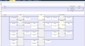
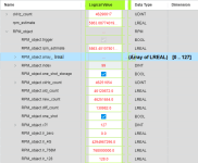
Anyway, see below for what I came up with.

  • I used bit 9 of the 100kHz (10µs) counter from the RHC instruction as a test,
    • which should have a rising edge every 10240µs = 10.24ms,
      • so the frequency would be ~100Hz,
        • or, at one pulse per revolution,
          • it would be 5859.375RPM (= 60 * 1e5 / 1024),
        • and that is what I see, ±0.2% or so.
  • It calculates the RPM on every rising edge of the trigger,
    • using the 100kHz counter timestamps for the current edge and the 128th previous edge,
      • for a time base of just over a second (1310.72ms).
    • For only 3-4 edges per second, that 128 would need to be smaller, of course
      • Unless a calculation with a 40s+ time base updated a few times a second is acceptable.
  • The 100kHz DINT counter rolls over about twice a day (4G * 1e-5 ~ 42950s; 1d = 86400s), but I happened to catch it, which is where the trends come from.

rpm_fb.png rpm_var.png rpm_main.png
 

Attachments

  • RPM_trend_over_25s.pdf
    166.2 KB · Views: 10
  • RPM_trend_4Gig_overflow.pdf
    142.7 KB · Views: 8
Last edited:
Stating the obvious

Just checking for sure - you are using DC instead of AC for the control voltage. The 8 milliseconds sounds like half of a 60 hertz power waveform.
 
>I think it will be 70RPM which will have a cycle of 285.71ms/pulse.

Let's first make sure we understand the signal generator.

If you have three equal-sized segments of a rotating "flag" being sensed by an inductive or optical sensor on a shaft turning 70 RPM, then the signal will be ON for 0.1428 seconds and OFF for 0.1428 seconds.

If you instead have three small "flags", then the pulses are shorter, but could be as much as 280-or-so milliseconds apart.

>And the frequency of the plc input is 8 ms.

It sounds like you're describing a filter value on the DC inputs of the Micro 820. 8 ms is the default filter on a DC input on the Micro 820 (and on most PLCs), and is used to reject induced noise from AC cables and loads in the electrical environment. One of our Forum members has a good video tutorial on the subject on YouTube. Right at the 1:35 mark, he shows that the Micro 820 can have that filter disabled by setting it for 0 ms.

The Micro 820 does not have all of the features of the Micro 830, 850, and 870 controllers. That includes built-in High Speed Counter features, and built-in High Speed Interrupts in hardware, which would be required for high frequencies in the kHz ranges.

It does have the ability to host a High Speed Counter "plug in" module, the 2080-MOT-HSC.

>on the micro820 I don't have the clockbits

All of the Micro 800 controllers have a "high speed clock" that is accessed using the RHS instruction. On the Micro 820, that clock increments by 1 every 10 microseconds. That is what our friend drbitboy has illustrated in detail in his posts.

And to my knowledge, all of the Micro 800 controllers do support Event Interrupts (EII). I have used input event interrupts to capture free-running clocks in order to calculate speed or frequency on other controller platforms, but not on the Micro 820.

But before we discuss other options, I think you should understand and describe the device that is generating the pulses to measure the shaft speed of your machine, so you know the actual timing performance your controller needs to provide.
 
I should also note that the usefulness of the estimate from my code degrades as the speed decreases, and it also makes a lot of assumptions, which are what Ken is referring to.

Also, it's an RHC instruction; RHS is a typo in the CCW help HTML, which refers to the wrong side of the road to drive on.
 
Last edited:
Thanks, I'll try drbitboy's approach in conjunction with my siemens rpm. I know that on the S7-1200 it works up to approximately 120RPM with negligible error.

I don't fully know the operating conditions of the machine, I know it operates between 10rpm and 70rpm. Right now to test, I have a 4m powerflex and a motor with rated RPM 1410, 50hz, 400v, 1.5KW running at 2.5hz.

https://imgur.com/a/PoszajX

In the Tia portal I'm going to catch the rising edge of the 5hz clock and I'm going to count these pulses.
I take the rising edge of the sensor pulses and count them.
As soon as I have 2 sensor pulses I will
#AUX_RPM := (#CTU_Pulses * 60) / (#CTU_Hz_Pulses * 0.2);
#CTU_Hz_Pulses := 0;
#CTU_Pulses := 0;

At the end I divide the value given by the number of pulses per turn.
just this and it works =D
 
Last edited:
All of the Micro 800 controllers have a "high speed clock" that is accessed using the RHS instruction. On the Micro 820, that clock increments by 1 every 10 microseconds. That is what our friend drbitboy has illustrated in detail in his posts.

And to my knowledge, all of the Micro 800 controllers do support Event Interrupts (EII). I have used input event interrupts to capture free-running clocks in order to calculate speed or frequency on other controller platforms, but not on the Micro 820.

The micro820 only has the STI(selectable timed interrupt), it does not have the EEI.
I still haven't managed to do the rpm counter and I can't assume values, I just have to transform the 3 pulses I get for each turn of the shaft.
If I understand correctly, can I use STI to create a program with the shortest cycle?
 
Thank you for pointing out that I misunderstood the documentation for the Micro 820. I checked in CCW this morning and of course you are correct that the Micro 830/850/870 models support event interrupts (EII), but the Micro 820 has only time interrupts (STI), User Fault, and Universal Plug-In Module interrupts.

Any time you are measuring speed with a sensor, you have to decide between counting the number of pulses per period of time, or time elapsed per number of pulses.

If this were my system, I would probably pursue the time per number of pulses approach and make use of the onboard free-running clock with its 10 microsecond (0.00001 second) integer counter.

I would use an ordinary DC discrete input and the RHC instruction to grab the number of 10 microsecond clock ticks at each rising edge of the proximity sensor input.

You have a three-bladed sensor flag, so the signal is probably divided into six equal periods of (60/70)/6 = 142.86 milliseconds. A rising edge arrives every 285.71 seconds.

You could choose to use every rising edge, or every three rising edges, or some other multiplier to grab the free-running 10 us clock value, and compare the new value the previous one. You will have to account for the roll-over of that clock twice a day.

The fewer pulses you use to trigger the clock value sample, the lower your precision will be. A 3-5 ms uncertainty in the moment of sample (because we are relying on the ordinary PLC program scan time) will have a larger effect if you're sampling every 285 ms than if you're sampling every revolution (857 ms).

I don't recommend using the pulses per period of time approach because your pulses are so long. If you measure pulses per second, when your 1 second time starts or ends, the sensor could be anywhere in a 142.86 millisecond stretch of ON or OFF state.

The most accurate way to do this function is to use a dedicated high-speed input circuit. The second most accurate way is to have an EII and a fast free-running clock. The third most accurate way is the fast free running-clock mechanism and a reasonable count of rising edges.
 
Last edited:
can I use STI to create a program with the shortest cycle?

You can, but I do not recommend it for this application.

Interrupting the ordinary scan every 1 millisecond (for example) just to slightly improve the accuracy of a slow shaft speed measurement feature is probably not worth the impact it will have on the rest of the control program.

The best use of an STI are totalizer or integrator functions where the precision of each time interval are important. They do work for "catching" a short duration signal, but that's not their main purpose.
 

Similar Topics

Hello, I've been trying to learn this a while now and still have not found out how this works. I have an Omron CJ2M PLC and an ABB ACS 355 VFD...
Replies
1
Views
251
Hello, I have to deal with iFix again and am looking at the most efficient way to create alarms to display in iFix, i.e. not creating an...
Replies
0
Views
159
Good morning to all, I have the following issue, I installed everything of intouch including the patch, it is the 2023 version. The...
Replies
0
Views
337
So, I finally got versioin 27 installed on my Windows 10 VM. However, now I can't upload a project from my lab controller. I have the above error...
Replies
0
Views
1,133
Hi all, I have few GB of logged data created by RS View 32 Works, it is all in .DBF format. At the moment, my company wants to shift all data to...
Replies
14
Views
1,464
Back
Top Bottom