Differentiating system versus user

afm

Member
Join Date
Aug 2023
Location
Tennessee
Posts
88
Hi all,

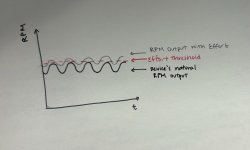
I am working on a project that needs to detect when a user is putting in effort into the system (this is a robotic gait trainer that functions similar to a elliptical). I am looking at the RPM of the motor to determine this. When the user inputs effort, an increase in RPM can momentarily be seen while effort is being exerted, and the HMI indicates that effort was made live.

Due to the system's linkage design, the RPM fluctuates through a range based on the users speed and step length (e.g. The motor is set to run at 25 rpm, but live readout of the RPM will be 22-27. When effort is exerted, you can see the the range shift to be 25-30).

Right now, my logic will scan motor for a 5 seconds, pull what the max RPM value is, and use that at the reference against the live read out, so in my example, if the RPM exceeds 27, the user has put in effort). However I want to try to make it more sensitive. For the RPM values that overlap in the NoEffort and Effort RPM ranges, is there anyway to differentiate between the effort vs. non-effort? I attached a rough sketch of what my HMI trend lines look like for each scenario. Thank you!
IMG_7914.jpg
 
Maybe it's an artifact of your sketch, but it looks to me that, when effort is applied, the amplitude of the trend decreases, so maybe that is a better metric. Also, the mean value seems to be raised as well.
 
Yes, both of those statements are true. When effort is exerted the RPM range usually gets tighter and the average rpm would also increase.

Currently, I am able to do a 5 second scan and pull what the minRPM and maxRPM is when no effort is exerted and find the amplitude from here. This will be my standard/reference amplitude value I will use to compare all my over values to. But since I want to give a live indicator of when effort is exerted, how would I find the "live" amplitude quick enough? and would I need an array to store these values for one cycle time?

I have also considered using the average as the metric to differentiate between effort and no effort, however, since users can change their speed settings throughout a session, I don't want to take a rolling average, since the past speed settings are irrelevant to current RPM values, if that makes sense. Thanks
 
If you were to use integration then you could find the area under the curve and this would give you a measure.
 
Hi all,

Steve Bailey, that's actually what I was using originally. I was using a motor current sensor with a current transducer on my driver. This has been working relatively well. Based on users settings (speed, step length, etc.), the sensor values will be within a certain range (graph is somewhat sinusoidal similar to the image in my first post. When someone exerts effort, you can see a drop in the current sensor value and trend line.

My logic was similar as described in the original post. I scan the device for 5 seconds to determine the minimum sensor value (reference point, minSV). If I apply effort, and the sensor value drops below minSV, then effort has been applied. This works accuratley, however, every time I change a setting (speed, etc.) I have to do a "rescan" to reestablish the baseline on the sensor. There is also a tiny bit of current decay that occurs after sometime in the device has been running for a few minutes that may affect the consistency of the program.

My though process was initially that since the current transducer and RPM output graphs are similar and both have a distinguishable change when effort is applied vs no effort, that RPM may be a good alternative that could reduce parts and/or rescans as long as it is just as sensitive as the current sensor. Does anyone have any thought on this?

And yes the only sensors I have relevant to this project is my encoder sensor to count RPMs and the motor current sensor.
 
Last edited:
It seems current gives the feedback you want here. What about the case where someone puts in exactly enough work to maintain the same speed? You'd have almost no current, but identical speed.

You've been calling it effort, but you should call it work. That makes things clearer: you want to measure the difference between work done by the machine and work done by the person. Since work is joules and joules over time is watts you should measure watts -- since voltage can be assumed constant, you're left with current.
 
How often can you read the sensor? You might be able to do better than wait 5 seconds to determine speed if you can get a sufficient number of scans per revolution.
Track the samples and detect each time the current sample changes from being greater than the previous sample to being less than the previous. Call that a reversal and measure the time between reversals. Two reversals equals one revolution. At 25 RPM you're at 2.4 seconds per revolution, 1.2 seconds between reversals. If you can sample at 10 milliseconds you should capture the time of reversal accurately enough to get a good calculation of speed.
 
The question for me is what is the character of the data? Are they smooth or noisy? If noisy, then to detect a max or min or reversal there needs to be a deadband, so sampled fluctuations (per-sample reversals) near a limit are not interpreted as reversals.
 
Something like this might do the trick.

The ∆ is the dead band magnitude, i.e. how far below the most recent maximum (HI) the RPM should fall to declare that HI as an actual local maximum, or how far above the most recent minimum (LO) the RPM should fall to declare that LO as an actual local minimum.


Each time it executes one of the
Code:
AMPL = HI - LO
statements on the right, that is a new max or min, so there will be a new amplitude value every 1.2s or so.
Untitled.png
 
Last edited:
Since the task is absolutely not clear, I will suggest the first thing that came to mind. blockhead-by solution

if abs(val_curr - val_prev)< max_sin_val_change_per_t then
begin
l1:=l1+k*(val-l1);
l2:=l2+k*(l1-l2);
l3:=l3+k*(l2-l3);
l4:=l4+k*(l3-l4);
{etc}
end
else
begin
l1:=l1+val_curr - val_prev;
l2:=l2+val_curr - val_prev;
l3:=l3+val_curr - val_prev;
l4:=l4+val_curr - val_prev;
{etc}
end;

To prevent possible noise-troubles, it may make sense to run this algorithm on timer…

sine_f.jpg
 
I am having a difficult time following the approaches that are being suggested. This is the first time doing data processing on a PLC and I would consider myself a beginner, so forgive me if I am slow to understand. I am using Ladder in Automation Studio for this program.

For more context, the machine has you input several settings for the user such as step length and speed (speedSet). There are other existing metrics like live speed (liveSpeed), live RPM (liveRpm), and the motor current sensor value (liveCurrentSV) that I can use (all three of these are noisy data, I want to determine the most reliable metric to use for this task). Due to the linkage system, the liveSpeed is not a constant value; it fluctuates +/- the speedSet value. The machine footplates (similar to elliptical linkages for simplification purposes) move regardless of whether work is put in by the user or not (many users have little to no motor function in lower limbs). The overall goal is to differentiate the machine work versus user work (as Cheeseface mentioned earlier).

When work is done by user, there is a distinguishable affect on the liveSpeed, liveRPM, and liveCurrentSV. For my task, I want to determine the sensitivity and reliability of each of these metrics to know which metric to use. From here, I want to be able to accurately pinpoint instances or periods of time where users are doing work on the device (a simple light indicator when work is done is fine for now).

Again, I have this working in a simple way with my motor current sensor. I have 5 second scan to determine the minimum current value, then use this reference against the live sensor values (liveCurrentSV< minCurrentSV = workDetected). Every time the speed is adjusted on the HMI, a "rescan" occurs to find the new baseline. The current sensor works fine, I just have concerns in case there is slight current decay during a session that would cause the reference SV to not be accurate until a rescan it triggered again. I would like to clean this up, reduce/remove rescans, and avoid oversensitivity of my "work detector" in case there is current decay.

I will add some images showing the live plot of the RPM and sensor values. Thanks everyone.
 
When the HMI speed (setpoint?) is changed, which initiates a 5-second re-scan to determine a new minimum current value baseline, how do you know the user is not doing any work during those 5 seconds?
 
When the HMI speed (setpoint?) is changed, which initiates a 5-second re-scan to determine a new minimum current value baseline, how do you know the user is not doing any work during those 5 seconds?

I don't, that is a concern of mine also. Other team members aren't as concerned with this and say that clinicians can tell patients to "go along for the ride" for a while, and indicate when to start working. But that is placing a lot of trust in the users. I would like to avoid any possible confusion and misuse of the feature. I understand that the very initial scan may be necessary, but I would like to avoid as many rescans as possible for HMI speed changes. It was difficult to make a highly accurate predictive model to calculate the new sensor value after a speed change due to motor start up time, current decay after its been "warmed up", and other factors.

I know that similar technologies to this machine have their own version of these "scan times" where for at least 30 seconds or so they have a calibration period to find this baseline. Clinicians tell patients to warm up and let the machine move to calibrate and establish those reference points.
 
Last edited:

Similar Topics

Hello, I have no training in maintaining potable water systems, so forgive me if some of my terminology is far off the mark or if I'm focusing on...
Replies
0
Views
96
I have a redundant ControlLogix being set up. This program reads a value from a remote site which happens to be SLC PLC. Rockwell mentions SLC...
Replies
2
Views
96
Hi all, This is going to be a long post apologies. I'm also a complete beginner to the world of PLCs. I'm currently working on my first ever...
Replies
10
Views
454
Hello everyone, I'm working on a project that involves controlling an array of nozzles within a CNC environment, where the nozzles travel along a...
Replies
5
Views
184
I am utilizing both HMI and SCADA for my project. Both HMI and SCADA have identical tags. When I modify the tag value on HMI, it is reflected in...
Replies
2
Views
156
Back
Top Bottom