Differentiating system versus user

I'm thinking of making a structured text program to execute the FIFO array logic. I know there are some FIFO commands built in for ST (attached an image of these).

The machine software has only used LD programs, so this would be the first time any ST would be used. Does anyone have input on how to go about that communication between LD and ST? I want that once my global variable "startArray" becomes true in my ladder program, it should execute the ST program that will handle the FIFO for loading and unloading the array, summing the array elements, and making the final determination (livePeriod < theoreticalPeriod = UserWorkDetected). How should this be approached and what other considerations do I need to make? There are other LD programs that will need to be running simultaneously as this one executes.

Thank you.

fifo.PNG
 
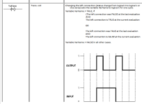
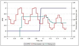
Sidebar: I was just looking at B&R's Automation Help, and under Ladder/Contacts, there is a -]PN[- contact, that outputs a one-shot (one scan cycle) pulse for both 0-to-1 and 1-to-0 transitions of its input operation. So if the current application used the encoder input as the operand (VarName) of that -]PN[- contact instruction, it would get 16 pulses per footplate cycle.
Untitled.png
 
Thank for this, i will add that in as an easy swap to get from 8 to 16 measurements per cycle.

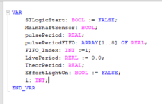
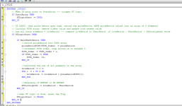
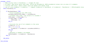
I have this ST right now using an 8 element circular FIFO array (see attached). I have no compilations issues and all variables overlapping with my ladder programs are global. None of the ST code is running, even though the StartArray global BOOL is set to high, anyone see something I'm missing?

Few variables to note:
MainShaftSensor: the encoder sensor variable to check for pulses
EffortLightOn: variable for user work being detected to display on HMI

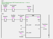
ST1.PNG ST2.PNG LD1.PNG
 
Last edited:
How are you calling the ST program?

Or has it been placed in a list of programs to run, as part of the continuous task, or as part of a timed interrupt task?
 
How does the Boolean MainShaftSensor get assigned a value of 1?

I don't see any point to copying the value of StatArray to STLogicStart, but it should not cause the code to not run
 
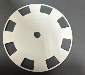
Yes, it isn't the cleanest right now. The MainShaftSensor is an inductive sensor that is sensing the metal from the encoder wheel (attached). When detecting metal, MainShaftSensor get assigned a value of 1 (what I was referring to as encoder wheel pulse sensor earlier).

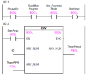
I made some changes to the ST to execute the array while StartArray is true and to eliminate the unnecessary STLogicStart variable (attached). I havent called the ST program anywhere explicitly...that may be an issue. I thought the StartArray global var being true would start the ST execution; do I have to do this in the LD with a FB? I will look into the communication to call the ST from the LD program.

LD1.PNG ST2.PNG IMG_8185.jpg
 
Last edited:
Another update, when running the program to test, when the StartArray went true, the machine stopped and PLC went into a service mode. It was resetted when I power cycled the device. Is the PLC getting confused by which logic to run?
 
Last edited:
Another update, when running the program to test, when the StartArray went true, the machine stopped and PLC went into a service mode. It was resetted when I power cycled the device. Is the PLC getting confused by which logic to run?


The fix: change that "WHILE ... DO" to "IF ... THEN."

The error
... is most likely a watchdog timeout.

  • On the first scan cycle when the StartArray Boolean became 1, the WHILE-DO-END_WHILE loop never ended
  • The ST program CYCLIC never returned on that scan cycle
  • The scan cycle timer continued to rung until it hit its preset limit (probably 100ms or 500ms or 1000ms or some such value)
  • The PLC watchdog timeout detected that that scan cycle was to long and halted the PLC.
Bottom line: everything worked exactly as you told it to.

For further study: find out what a PLC scan cycle is.

Lesson learned: The only thing worse than the PLC not doing what you want it to do, is when it does exactly what you tell it to do.
 
Thank you for this, I don't have any guidance for the project so this is definitely a learning experience talking to everyone on here.

I had a few issues with some variable calling as well but the ST is working now. I've watched the program live and can see the FIFO filling and updating as I wanted it too. The user work detection seems to be working well for lower RPM setpoints, but the higher RPMs tend to calculate a higher livePeriod, so unless very high user work is done, it is difficult to trigger the user work detection (HMIgreen light display).

I have a few thoughts/theories on the causes.
1. This program is running at cyclic of 100ms. For higher RPMS, the scans are occurring too slowly. Potentially reduce this scan time, the motor runs on a program of 1ms, would this need to scan that quickly also?

2. I am still using 8 measurements/rev based on leading edge of that encoder wheel sensor. Will switching to 16 measurements help or worsen this livePeriod calculation overestimation? And will my 100ms scan time be able to read, store, and sum these 16 measurements fast enough?

3. Would setting up an interrupt for every high pulse on the encoder sensor help over a continuous scan like I have now? I am not familiar with these, but I am willing to try that if is a better option.

Any input or advice on next steps would be appreciated, thanks! :)
 
1. For a process cycling with a period of around 2400ms (25RPM), a PLC scan cycle period of 100ms could be too slow and introduce aliasing into the sampling.

2. Increasing the triggers per cycle should change only how frequently the liveRPM calculation is made, not the results or the character of the results. Whether the PLC processor has the computational reserve to handle that increase is unknown*. There would be a trigger every 150ms or less, so with a scan cycle period of 100ms it is approaching the limits of a rising AND falling edge detection instruction.

* 2.1 instead of calculating per-trigger periods, and then summing 8 or 16 periods, at each trigger event, it would take far fewer calculations to put the absolute time of each trigger event into the FIFO, and then calculating the period from the oldest absolute time (before it is overwritten) from the current absolute time, at each trigger event.

3. An interrupt routine would almost certainly be a much better way to do this, as it would greatly reduce the sample aliasing. That said, if you convert to an interrupt scheme, I strongly suggest using the algorithm in 2.1 above, or at least restrict the code in the interrupt routine to only update the FIFO, and perform the rest of the calculations in the 100ms scan cycle.
 
Last edited:
1. The device can run up to a max RPM setpoint of around 36-37 rpm, and if we watched that setpoint RPM live it would likely be in a range of something like 35-40 rpm. I switched the task class to 50ms and did not see any observable difference from 100ms (still, lower rpm detected user work accurately, higher RPM were under sensitive.) I then made it a 20ms scan time and it is currently running well for both lower and higher RPM... however that is only for lower stride lengths. There are actuators that can adjust the "stride length" of the steps from 10 to 24 inches based on used height. As I ran the device on lower stride lengths (10-14 in) it ran well, but larger ones like 17 inches+ showed "spikes" of user work when no work was done... Aside from task class adjustments, the program remained the same. I like this approach to use the period, but I am unsure of next steps.

2. I understand, so instead of 8 triggers occurring in 1 revolution, 16 triggers are within 1 revolution. So the array would need to hold 16 elements. I think the reason why I am confused is because the pulsePeriod is the time from one rising edge of the sensor to another, so that is 8 measurements per revolution. So if I increase my trigger from 8 to 16, wouldn't I need the ON and OFF time to use to store the FIFO in order to have 16 elements rather than the time I am using now? Not sure If I explained that well enough.

2.1 Could you elaborate some more on what is meant by this approach?

3. I believe interrupts take precedent when scanning? As long as there wont be conflicting programs, I could try. How/should I adapt my ST code for this?

Thank you again.
 
1. Doesn't a longer stride length imply a slower base RPM, assuming a constant MPH? If yes, then a longer stride should be easier for the PLC to handle (longer time between encoder transitions). So the result that longer stride length generates spikes seems odd. How are you calculating the pulsePeriod? I.e. what are you using for a clock to measure the time between encoder edges? What is the resolution of that clock (how many bits; how much time is represented by each tick)? Does that clock "roll over" i.e. reach its largest possible value (all bits are 1) and then increment to 0 on the next tick?

2. For the eight triggers per cycle used now, I assume you are calculating the pulsePeriod between each successive pair of rising edges. For sixteen triggers, you would need to calculate the pulsePeriod between each rising/falling and falling/rising pair of edges.

2.1. In the current code, at each rising edge, you subtract the absolute clock time of the previous rising edge from the current absolute clock time, call the current pulsePeriod, and put it into the FIFO, so the FIFO looks like this:

  1. pulsePeriod from 8th previous edge to 7th previous edge
  2. pulsePeriod from 7th previous edge to 6th previous edge
  3. pulsePeriod from 6th previous edge to 5th previous edge
  4. pulsePeriod from 5th previous edge to 4th previous edge
  5. pulsePeriod from 4th previous edge to 3rd previous edge
  6. pulsePeriod from 3rd previous edge to 2nd previous edge
  7. pulsePeriod from 2nd previous edge to 1st previous edge
  8. pulsePeriod from 1st previous edge to current edge
Of course, those values shift at each edge because you are using a circular array as a FIFO, but that does not change anything.

You then sum those eight elements' values to get the total period from the 8th previous edge to the current edge i.e. 1 cycle period. Finally you save the current absolute clock time as the previous absolute clock time so you can calculate the next pulsePeriod at the next edge which will occur in a couple hundred milliseconds or so.

What I am suggesting is that, instead of calculating each individual encoder pulsePeriods and summing them to get cycle period, you could instead store the absolute clock values at each edge into the FIFO, so the FIFO would look like this:

  1. absolute clock time from 8th previous edge
  2. absolute clock time from 7th previous edge
  3. absolute clock time from 6th previous edge
  4. absolute clock time from 5th previous edge
  5. absolute clock time from 4th previous edge
  6. absolute clock time from 3rd previous edge
  7. absolute clock time from 2nd previous edge
  8. absolute clock time from 1st previous edge
Then, to get the current edge's cycle period, you can do one subtraction, i.e. subtract the absolute clock current absolute clock time from the 8th previous edge from the current absolute clock time. Finally you overwrite the array location with the absolute clock time from the 8th previous edge with the current absolute clock time, and then wait for the next edge.

The FIFO array encodes the same information, albeit in a different way, that requires fewer calculations and allows for simpler code.

3. To adapt your current ST code, make it the code that is called by the interrupt. I would change the code to save two absolute clock times outside the FIFO array: the current time of the latest interrupt; the time of the 8th previous interrupt to that which was overwritten by the latest time. You would also need to update the circular pointer into the FIFO. The details will be specific to your current brand and model of PLC. You will no longer need to detect edges in software to trigger the execution of the ST code as the interrupt handler will take care of that.
 
Your other thread about accumulated effort has made me think about what you're trying to measure. As I see it there are two possible types of effort. The first is that the person on the treadmill is trying to get ahead of the motor. For that type of effort, the motor current should drop compared to the baseline current. The other type could be classified as wasted effort. In that case the person on the treadmill is fighting the motor, in effect trying to slow it down. That would show as an increase in motor current compared to the baseline.
Now, if your project is help the person more efficiently use the treadmill, then distinguishing between the two types of effort is worthwhile. If the objective is to measure the energy expended by the person, then it doesn't matter whether the effort is aiding or opposing the motor.
 

Similar Topics

Hello, I have no training in maintaining potable water systems, so forgive me if some of my terminology is far off the mark or if I'm focusing on...
Replies
0
Views
96
I have a redundant ControlLogix being set up. This program reads a value from a remote site which happens to be SLC PLC. Rockwell mentions SLC...
Replies
2
Views
96
Hi all, This is going to be a long post apologies. I'm also a complete beginner to the world of PLCs. I'm currently working on my first ever...
Replies
10
Views
456
Hello everyone, I'm working on a project that involves controlling an array of nozzles within a CNC environment, where the nozzles travel along a...
Replies
5
Views
185
I am utilizing both HMI and SCADA for my project. Both HMI and SCADA have identical tags. When I modify the tag value on HMI, it is reflected in...
Replies
2
Views
157
Back
Top Bottom