GE 9030 - IMS- Powerfold sheet metal bender

bits like B03<-21 I am clueless about
Those are names the program's author assigned to the discrete points. In a current software package they would be called tagnames or variable names. In Logicmaster they were limited to seven characters. I'm equally clueless by what the author had in mind.

To see more of your documentation on screen, hit <ALT> + N repeatedly. That will cycle through the various display options. You can look at just the nickname (which is what's displayed in your screen shot), the address, the nickname plus the three-line reference description, or the address plus reference description. The one thing you can't get on the screen at the same time is the nickname plus the address.

The IC693APU302 motion controller modules use a mixture of discrete input (%I), discrete output (%Q), analog input (%AI), and analog output (%AQ) addresses. The manual for the module is GFK-0840*, where * is the revision letter. I believe the last revision was GFK-0840D.

There are 32 %I inputs assigned to each DSM302 module which give you information about the module and each axis. There are 32 %Q outputs per module. They allow you to command each axis from ladder logic. There are 27 %AI analog inputs per module. That's where you'll find your feedback information. Some of the returned data (like axis positin and velocity) will be in 32-bit integer format which means the data takes up two consecutive %AI addresses. Finally, the module uses six %AQ analog output words, three words for each axis. You can use those to command specific motion like moving to an absolute position. The meaning of each of the addresses is covered in chapter 4 of the manual.

As to your referencing issue, I've seen cases like yours where the axis stalls trying to find home. The position error is small and the servo drive can't generate enough torque to overcome the frictional drag. You may need to increase the position loop gain or the homing speed. You'll find those parameter settings in the hardware configuration. Module configuration is covered in chapter 3 of the manual.
 
Steve,

Awesome post. A lot of fantastic information. I've been moving in the right direction, but you just put me about 10 miles ahead of where I was.

First, the Alt-N will help a lot.

Second, I can see now that a lot of conditions the rung needs to move to the next step come right from the servo in the %I. I will have to dig into the config on the module more to perhaps shed some light on what things like B03<-21 means.

Where the press hangs up is when the head is fully closed. During homing it runs full open. At full open, it defines position as 24". I measured and indeed it is 24". The next step the press runs full closed, to mechanical stop. It does read zero, so I know the position encoders are working, but it acts like it wants to keep going even though it is fully closed. I'll do some more tomorrow morning armed with this information.

I think also since this stuff is so old, I'll use this post as a sort of blog just in case someone else out there ends up fighting a similar issue.

Again, thanks for all the information. Can't say thanks enough.
 
Does anyone know if it is possible to toggle, or force bits?

It looks like under the "debug" it would be possible to do this, but the menu option is not available to me when I zoom into the ladder logic portion.
 
Does anyone know if it is possible to toggle, or force bits?

It looks like under the "debug" it would be possible to do this, but the menu option is not available to me when I zoom into the ladder logic portion.

Have you tried selecting a bit in the ladder and press, F11 and/ or F12 one "Over-rides" a bit the other toggles it.

This is a guess but logical. B03<-21 means that B03 is less than negative 21, as this is a bender it likely means that Bend number 3 is less that -21 degrees. It appears that the others will be similar. You should be able to tell where they come from by checking the names of variables for whatever monitors the bend.
HTH
 
Last edited:
"This is a guess but logical. B03<-21 means that B03 is less than negative 21, as this is a bender it likely means that Bend number 3 is less that -21 degrees. It appears that the others will be similar. You should be able to tell where they come from by checking the names of variables for whatever monitors the bend."


I thought perhaps this was true as well, however, the description for B03<-21 is "c.b.l. program active".

c.b.l. = clamping beam left. This much I'm confident in. I think B03 might = axis 03. But I'm so ignorant of the axis config yet that the -21 value means little to me.

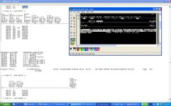
Judging by the rung and what is true and what is false and keeping the press from activating CB_RF06, it sure looks to me like the press is still trying to finish a move of the clamping beams before it will go to the next step. Attached is a screenshot of the rung I posted earlier, but with the descriptions showing. Makes it a bit easier to digest the state of the rung.

You can see that the the 2 axis are not moving, but they do have a program active, and neither says they are "in zone". Thus, I'm thinking the servos do not think they've completed their move. I've also seen some evidence that these also would help trip the "PRESS>MAX" requirement and make the "Buildup Pressure" bit true as well. I think I'm going to have to learn what the servo is really trying to accomplish and why its not able to.

I will try the toggle option tomorrow. That may help.

Logic Screenshot with printout.jpg
 
Those "program activ" bits with %I addresses are coming from the motion controller module. They indicate that the module is in the middle of executing a stored motion program. If you drill down into your hardware configuration for the module you will find Program 0 which gets started by turning on one of the %Q bits associated with the module. There is also the potential for additional stored programs launched by turning on other %Q bits. If those additional programs exist, they were created using the Logicmaster Motion Programmer, another Logicmaster add-on. The additional motion programs are designated Program 1 - Program 9. Those programs are stored in the motion controller module's RAM which is backed up by the same battery that backs up the CPU modules RAM. The battery is located on the power supply module. If the motion module has been removed from the backplane, you've probaly lost any stored programs in the Program 1 - Program 9 range. If the ladder logic is calling for one of those programs and it no longer exists, it might explain the baehavior you're seeing.

I suggest you check the manual to identify the %Q bits associated with those stored programs and search the logic to see if any of them are used. Sorry, but I'm not sure exactly which %Q bits start the stored programs and I don't have the manual available where I am today.
 
Steve,

No need to apologize. Your posts have been immensely helpful thus far, and I expect nothing. Anything you've added has been a bonus.

I don't think that any of the extra motion programs are used. I did a search on all of them and see no place where they are used.

Right now I'm mostly focused on understanding the parameter configs on the axis in question. I can see the actual position. Just not 100% following the command word configuration and the "in zone" word definition. It's very clear to me that the axis is in the middle of a move. I'm just not clear on where it needs to go, how close it is, etc. Those will be useful pieces of information when I get it down.
 
Another newbie question. There are bits shown like this that are expansions of function block steps. Can anyone tell me what the .X bit is?

PCBD1.x %T0222
+--] [----------------------------------------------(S)--
 
The PCBD1.x bit indicates that the PCDB1 step is active. There is also a PCBD1.t word (16-bit) that is the step timer and a PCBD1.f bit which indicates a fault in the step. Two faults are defined for each step, either too long active or transitioned out before reaching minimum time.

The attachment is a power point presentation I put together on Logicmaster SFC. Just change the file extension from .zip to .ppt.
 
I have same machine with same issue

Was there ever any resolution to this issue, I am working on a powerfold with same issue.
 

Similar Topics

I have lm9030 program on my toughbook CF-29 cannot get my program to hook up with the serial port.
Replies
2
Views
71
how do you load from [A] floppy disk to laptop 9030 program
Replies
3
Views
152
Replies
1
Views
116
We have a customer that has 6 machines running GE Series 90-30 PLCs. In order to support them, they bought a used Dell Full size desktop PC with...
Replies
4
Views
1,246
Back
Top Bottom