Learning by Doing

Your drawing looks fine to me, Arik. This idea is a familiar one to me. I've done some work with customers that use a lot of web-handling lines (plastic film, mostly), and they use this method quite frequently (they had a name for it, but it escapes me at the moment). It does do a good job of smoothing out the line.

I don't think that it's practical for this application, however, given how stiff the wire is. I think it could only be useful on a very large piece of equipment, where there is ample room for the material to assume a more natural bending radius. I have about an 8" long sample of this wire here at my desk and it's all I can do with my bare hands to deflect it about a 1/2"
 
elevmike said:
I'm gonna say that I'm not convinced that a stepper will have the necessary power for this system.

You could be right, Mike, but I've seen some pretty scary-looking ones, with pretty impressive torque output curves. They also come with some monstrous current requirements, and a pretty scary-looking price tag. You may have hit on the biggest disadvantage earlier when you pointed out that the DL06 may require an expensive auxiliary module to use them with an encoder.

On the other hand, I've been studying up on AC drives this afternoon, and I was astounded at how far these things have come since I last worked with one -- they're so compact, and you can do so much with them! And I do like the idea of being able to use an off-the-shelf three-phase motor.

At any rate, we may be getting too far ahead of ourselves in sizing a drive system before having all the data to calculate the torque requirements. Although I guess it doesn't hurt to weigh the pros and cons a bit at this stage. Would be nice though to be able to just build the machine, load a roll of wire on it, and put a torque wrench on the input shaft. 'Course, what does that say about my skills as an engineer? (Probably nothing that hasn't been said already! :p )
 
pstephens said:
Although I guess it doesn't hurt to weigh the pros and cons a bit at this stage. Would be nice though to be able to just build the machine, load a roll of wire on it, and put a torque wrench on the input shaft. 'Course, what does that say about my skills as an engineer? (Probably nothing that hasn't been said already! :p )

pstevens, Regarding the extra counter $200.00 isnt all that expensive figuring the all the costs as a whole including potential for failure, added time etc... You might have to check with AD support or download the manual on the H0-CTRIO counter to see if you can use both counter modes 20 and 30 at the same time.

Ok regarding you drive system. I'm thinking you might get the torque by gear reducing 4 : 1. That is for example the pully on the motor shaft will have a 1.5" pully; the drive sprocked with have a 3" OD on the timing belt, and a 1.5 OD on the friction sheave for the wire. I drew this up but My CAD is an old DOS based program, and I'm having trouble doing a screen print from it so I cant post it right now. So I hope you get the "picture". Anyway by the time the motion gets down to the sheave thats driving the wire, its going 4 times slower then the motor. This will multiply the motor torque by 4 x; of course sacraficing speed. The right gearing might get you back to the stepper idea if you can use mode 20 & 30 at the same time.

Anyway Stock Drive Products sells timing pully stock that can be machined so that you can make a pully with a shoulder for the pinch groove for driving the wire. You can get it in plastic, alum, or carbon steel. Check with them.

I'm not so worried about the torque required to turn the reel, but the added torque required to pull the wire through the pinch point between the driver and the tension sheaves. In an effort to grip the wire your going to have a considerable amount of pressure between the two sheaves, which will when added to the load of the reel might be considerable. This may be reduced by adding a friction surface only to the wire groove on the driver. This will also harden the surface. We send our stuff to Surf-alloy. Authough they do not spicificly address it on their website they do this kind of work for us often. They'll have a good idea how to help you with it.

Dont make fun of your self regarding the toque wrench thing, I do that all the time, in addition to using fish scales etc.. Just takes out some of the guess work, and eliminates errors in calculations.

Later...
 
I mentioned that I worked in steel plants that worked with wire making threaded rods etc. On their wire puller systems the wire rolls were 2500 lbs or greater and rewound onto metal stands. The rewind sometimes used a simple turntable with a 90vdc gearmotor.

Sounds like it may be possible to use a simple DC motor or gear motor with a controller that could accept a 0-10vdc speed reference from an analog output.

Simple inexpensive option that wouldnt hurt to look at, W W Grainger http://www.grainger.com offers a variety of 90vdc motor, gearmotor and controllers.

This would also allow it to run from a 120vac outlet. This controller is good up to 2HP with max of 10amps with speed range of 50:1 http://www.grainger.com/Grainger/productdetail.jsp?xi=xi&ItemId=1611787082&ccitem=

Just a thought.
 
elevmike said:
I drew this up but My CAD is an old DOS based program, and I'm having trouble doing a screen print from it so I cant post it right now. So I hope you get the "picture".

I'm hearing you on this. I have three different versions of my CAD program (Cadkey), but the old (ancient, in computer years) DOS version is the one I prefer to use. The two newer Windows versions can't even begin to compare in speed and ease of use to the DOS version. The Windows versions must be processed through the bloated Windows GUI, while the older DOS version writes directly to the screen. But when I want to create a picture file, I have to import the vector image into the newer program.

Anyway Stock Drive Products sells timing pully stock that can be machined so that you can make a pully with a shoulder for the pinch groove for driving the wire. You can get it in plastic, alum, or carbon steel.

Good advice. I've got one of their catalogs, and have worked with them before. I also use a lot of Browning components.

I'm not so worried about the torque required to turn the reel, but the added torque required to pull the wire through the pinch point between the driver and the tension sheaves. In an effort to grip the wire your going to have a considerable amount of pressure between the two sheaves, which will when added to the load of the reel might be considerable.

You could be right about this, but my gut feeling is that the resistance added by the force between the wire and the driving rollers will not be so significant. The drive roller shafts will be mounted on ball bearings, and the pressure forces will be acting at right angles to the torque vector. There will undoubtedly be some added load to the total system, but I don't think it will be of a much smaller magnitude than the inertial forces involved.

This may be reduced by adding a friction surface only to the wire groove on the driver. This will also harden the surface. We send our stuff to Surf-Alloy.

I will definitely look into this.

Dont make fun of your self regarding the torque wrench thing, I do that all the time, in addition to using fish scales etc.. Just takes out some of the guess work, and eliminates errors in calculations.

Don't worry, I always prefer actual, tangible test data to theoretical calculations. Here is one of my favorite tools -- a Dillon Quantrol digital force gage. It reads both tension and compression in pounds, ounces, kilograms, and newtons, up to a maximum of 45 lbs. Quite handy!

QUANTROL.jpg
 
Last edited:
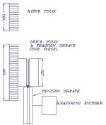
Here's my preception of how the drive will look from the side/end view. Take notice that the wire driver has a V groove. This will insure that the wire is making contacts with two points on the driver. If it were a U groove and the wire wasnt a perfect fit, being maybe a smiggen smaller.. the wire would only make one contact point on the driver.

wirefeed.jpg
 
Last edited:
westoes said:
is there a chance to set up an adjustable sensor for length required ie.pe cell,proximity or limit switch,that the operator moves into position on start up ?.obviously for ultimate accuracy an encoder in a closed loop system is the way to go.

Actually, this is not that much different from the method that they are currently using, and it is something they would like to get away from. I think my customer is sold on the elegance of metering the wire to a preset length, however less direct a method it might be. They also want to get away from having to reset mechanical stops/sensors each time they change lengths. Anyway, thanks for the suggestion.
 
Originally posted by rsdoranIf the customer is agreeable to using surplus items in the design you may be able to offer more system for the same money.

I'll admit, that's an idea I hadn't considered. But I'm a reluctant to go that route on this particular project. Control systems (for the time being, at least) are not my forte, and I feel like I need every break I can get as far as support from the manufacturer goes. You more experienced types are probably in a better position to take advantage of surplus stuff.

The Oriental stepper motors I used to work with were the 5-phase that included an encoder. These were overall reliable units but I can state don't cheat on the wire (go too small) especially if the units are not stationary. These units were very precise in positioning.

I have to say I'm also kind of impressed with Oriental Motor. I saw one of their ads in Machine Design, and must have circled their number on one of those literature-request cards. I usually do this if I'm only mildly interested in their ad, as there seems to be about a 1 in 10 shot of them responding. Well, they responded by sending me a copy of their 2" thick catalog -- very impressive and well-documented. Not long after, I got a call from one of their sales technicians asking if I needed any help with an application. Though I haven't priced any of their stuff yet, my guess is that's where the trade-off is. Looks like they really have their act together, though.

I did some work for a company that made threaded rods... I cannot remember the company names of the machines that cut the wire prior to threading tho. I noticed that this company, http://www.threadedrod.com/index.php also makes threaded rod if the process is similar and you could get a tour you may get some more ideas.

Actually, this place is not far from where I live.

The machines I remember used regular AC drives with feedback from a counter or encoder and brakes to do a feed to length then cut style system.

This is the approach that Mike was discussing yesterday, and it looks like it might work well for a machine like this. I wasn't even thinking of an alternative to the stepper. I didn't realize how much you could do with an inverter these days. Arik suggested a Yaskawa J7, which is a nice-looking little unit. I haven't a clue how to interface on of these with a PLC, however.

Sounds like it may be possible to use a simple DC motor or gear motor with a controller that could accept a 0-10vdc speed reference from an analog output. Simple inexpensive option that wouldnt hurt to look at...

I wonder about this too. Really, as long as one monitors the actual wire travel with an encoder, just about any motor that can stop predictably and be controlled from the PLC is worth considering. My problem is I don't have a great deal of experience with most of them. I've been studying up on steppers for a month or more now, and I may wind up going that route just by default, and the need to make some kind of decision.
 
Last edited:
elevmike said:
Here's my perception of how the drive will look from the side/end view.

Neat drawing, Mike!

Take notice that the wire driver has a V groove. This will insure that the wire is making contacts with two points on the driver. If it were a U groove and the wire wasnt a perfect fit, being maybe a smiggen smaller.. the wire would only make one contact point on the driver.

This is an excellent point. Practically speaking, the U-groove would have to be designed larger than the wire diameter, to allow for the tolerance on the wire diameter, affording only a single line of contact. You're right, the V-groove would guarantee that you always have two contact points, regardless of wire diameter variations. I would design the V-groove roller with a very slight throat radius, however, to prevent cracking during heat-treatment.

Another thing I'm strongly considering is gearing the rollers on either side of the wire together. A stock spur gear would be mounted directly below each drive roller, keyed to the same shaft. When the drive rollers are engaged, the gears would mesh together at the proper pitch distance. Having two stations like this, driven together thru timing pullies (like my drawing in post #15 shows) gives me eight driven contact points on the wire. If an encoder needs to be added, I would use a separate idler roller. This would allow me to size the idler roller driving the encoder somewhat smaller than the drive rollers, for higher resolution.
 
pstephens said:
I wasn't even thinking of an alternative to the stepper. I didn't realize how much you could do with an inverter these days. Arik suggested a Yaskawa J7, which is a nice-looking little unit. I haven't a clue how to interface on of these with a PLC, however.

The DC or AC drive would take let's say 5 digital inputs from the PLC. Forward, Reverse, High Speed, Low speed/creep and Stop/hold.

You would setup the inputs on the drive to provide the actual speed amd direction you want that input to provide. It's actually rather simple.
 
Last edited:
pstephens said:
I would design the V-groove roller with a very slight throat radius, however, to prevent cracking during heat-treatment.

You could do this but the Surf-aloy treatment, or someting like it would only harden the surface of the inside of the groove, not much deeper than a few thousands of an inch. It would provide for a hardened traction surface only. If you harden the entire part, it would be diffucult to do machining on later if you needed to make any unexpected alterations.


pstephens said:
Another thing I'm strongly considering is gearing the rollers on either side of the wire together. A stock spur gear would be mounted directly below each drive roller, keyed to the same shaft. When the drive rollers are engaged, the gears would mesh together at the proper pitch distance. Having two stations like this, driven together thru timing pullies (like my drawing in post #15 shows) gives me eight driven contact points on the wire. If an encoder needs to be added, I would use a separate idler roller. This would allow me to size the idler roller driving the encoder somewhat smaller than the drive rollers, for higher resolution.

Personly, in my own opinion.. all this would be unnecessary. You will have two drive rollers and two idlers/tension rollers. If done right this will provide good traction. The cost and coplexity of the driveing unit would be much lower. The encoder does need to be placed on an idler sheave so that you wont measure slip between the drive and the wire. IMHO...

Additionally you want the Surf-Alloy surface to be HARDER then the wire. This will allow the driving surface to byte into the wire for good traction, and eliminate wear on the driving surface.
 
Last edited:
Paula

Dont be worry about the interface with J7.
You need 2 outputs and 1 input,With DL06 you have enough.
 
Last edited:
I've got to admit to being fascinated by this thread.

It deals with an area where I have absolutely zero knowledge, but nonetheless it's been unbelievably interesting to watch the suggestions grow and develope.

It's a perfect example of why I believe this forum to be one of the best on the net, regardless of area of interest.

I feel really privileged to be able to participate here.

Many thanks to all concerned!
 
Arik,

Please pipe in if you think better about the drive motor issue here I dont commnley work with stuff this small so your, or others input would be of value.

With that said.. I say five inputs to the drive like this:

2 for direction, forward and reverse. (Just in case of overshoot)
1 input for high speed to take off and accelerate.
1 input for slowdown to creaping speed.
1 input to plug the motor, or in the case of a dc motor to fully energize the field. to hold the wire in place for cutting.

Hence 5 inputs.

Also if you wanna get more involved you can use an analog output from the plc to provide a reference to the drive but that's really sophisicated for this.
 
Couple of more thoughts...

1) You may not need the clamp if your able to achieve good traction; the drive unit and motor could hold the wire in place for cutting.

2) I see the two pinch rollers on a rocking bar, that is attached to a guide, that would be forced up by a heavy coil compression spring. The tension could be adjusted on the spring.

3) You may want to add two more buttons to your panel, Jog Forward, and Jog Reverse. They would be used to assist in feeding the wire through the drive unit. ??? The jog buttons would be programed to drive the unit in low speed only.

4) You may also want to add another button to initiate the encoder count. Like when you first install the wire, you would manually jog the leading end to the shear then press the reset button to zero out the encoder.

Your program could also keep track of the total amount of wire used by accumulating the lenghts of each cut. This value would be stored in retenitive memory. This way you can display the amount used, or left on the reel over time. So lets say theres only 10 ft left on the reel and the cuts are 11 ft long. the unit would automaticly stop before pulling the end off the reel. This value could be accumulated for days or weeks until the reel is used up. You can also display if you have enough on the reel to complete the current job. On and On and On etc... The total used count would be retained even with the power off.

Just a thought.
 

Similar Topics

Hello everyone. I am currently doing a project to teach about ethernet topologies such as ring or bus. For example. But instead of using an...
Replies
8
Views
4,346
Although I did not title it as such the last chapter would have been the PID. Learned a lot will give the details in that post. SO on to the...
Replies
20
Views
10,566
I've gotten to the learning curve where I can program a call for pump to come on at set point but I'm not sure how to turn the same pump off when...
Replies
1
Views
139
I want to pick up an Allen Bradley PLC so I can practice writing programs. I have 10 years as a maintenance tech and a good understanding of...
Replies
8
Views
238
Hi all, i have started a new chapter in my career with a local company. a lot of their plc's is omron and i have the cx version 9.75 software...
Replies
25
Views
4,235
Back
Top Bottom