Relay outputs for solenoid valves

Not content to let a good argument go by let's not forget about another difference between AC and DC coils which have moving cores. On the AC the core is not pulled in at startup. There is a high current. Then, as the core pulls in, the impedence of the coil at 60HZ (or whatever the rated frequency) rises and the driving current lowers with the eventual holding current being less. A DC coil experiences no such change in impedence even though the core still pulls in. Thus larger DC contactors sometimes have a pull-in and a holding coil, the pull-in coil being disconnected once the contactor makes leaving the holding coil energized at a much lower current.
 
Regarding Inrush Current...

At the instant that any type of voltage is applied to any type of circuit, the voltage "sees" only the inherent ohmic-resistance of the circuit.

If there happens to be only a coil in that circuit, then, initially, that coil is seen to be as essentially a DEAD-SHORT! The resistance to current flow is limited ONLY by the ohmic-resistance of the wire of the coil. The wire of the coil could just as well be a wire that is stretched straight for its entire length.

With respect to the ohmic-resistance, current WILL BE what the ohmic-resistance allows. With respect to any coil that might be in that circuit, it is only through TIME that a Counter-EMF is developed to restrict current flow. That is, at initial closure of the supply contactor, the current WILL BE whatever the fundamental ohmic-resistance of the circuit allows! Again, that means, current WILL ATTEMPT to go from Zero to Maximum, "INSTANTANEOUSLY", that is, in zero-time! That is called a "SPIKE"!

It is only after TIME passes (this is illustrated very well in Calculus) that the coil develops a Counter-EMF, increasing from zero, thereby appling "additional" resistance, gradually, to the initial current flow.

At a certain point in time, associated with the "henries" of the coil, the current will stabilize.

The bottom line is...
There is Rush Current in ANY kind of coil under ANY kind of voltage - IT'S THE LAW!
 
I might as well beat this topic to the ground

Terry

There is Rush Current in ANY kind of coil under ANY kind of voltage - IT'S THE LAW!

I am not sure what law you are referring to but it is not a law of physics or electricity that I have heard of.

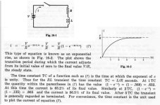
The following was copied from Electric Circuits by Joseph Edminister.

[attachment]

Using equation 7, the current i in Fig. 16-1 can be calculated for any time t after the switch is closed. I have deleted the calculus used to derive equation 7 as I want to keep the discussion as simple as possible.

When t is zero or very small, e -(R/L)t becomes e0 which equals 1 and i = V/R(1-1) = 0.

When t is large compared to R/L, e -(R/L)t approaches 0 and i = V/R(1-0) = V/R. This is shown on the graph in Fig. 16-2.

I hope this settles the inrush issue.

Vic

file0002.jpg
 
Last edited:
We may have another conflcit here between mathematics and reality, just like the fuse analysis on antother thread.

The reason I put snubbers on DC coils, when I do, is not because of the inrush current. It's because the coil stores energy. By the First Law of Thermodynamics, that energy has to go someplace when the contact opens. It will try to dissipate by arcing across the contacts of the relay or PLC. If you don't blelieve me you can watch the arcing in a relay with clear covers on an inductive load.

Now, I don't know about the time constants in the text book, but almost any coil data for a relay or solenoid or motor starter will show two currents - inrush and holding. The inrush is always higher. And I know that when you start an AC motor across the line the inrush current is way over the motor full load amps. I don't have the details to reconcile these known facts with the text and the mathematics - Someone help, please?
 
Last edited:
V/(0)?????

Vic,

"When t is zero or very small, e -(R/L)t becomes e0 which equals 1 and i = V/R(1-1) = 0."

Color me stupid but my two brain cells get a divide by zero error here. I guess it makes sense with current approaching infinity as indicated by the problem at hand.

Scott
 
I am not the sharpest marble in the bag, but ...

Current is limited in an inductor by cemf (the voltage opposite the applied voltage, which is generated by the expanding magnetic field, which in turn is a result of changing current flow).

At time 0 when current flow is initiated the rate of change of the magnetic field will be at a maximum > the cemf will also be at a maximum limiting the rate of increase of current. The curve Vic displayed is correct...

...but the moment you toss an armature in the middle of the coil you have just changed the impeadance characteristic. Now we have to observe the transformer action too. This is where the inrush current comes from.

The practical reason for snubbers is as Tom noted: to dissipate the energy stored in the magnetic field when the path for current flow is opened.
 
only 2 amps relay??

I think it is a electronic relay and not a contact relay.
so yes it would fry your relay inside plc and very difficult to repair.
so use a small relay or use a real switch relay inside plc (with modular wago or beckhoff).
we use 10 amp solid state relays for switching 24 volts ac in danfoss valves. these use only 2 amps. but now i can switch them every second.
 
Tom

I agree with what you say regarding what happens when the switch is opened. However, my post was discussing what happens when the switch is first closed. It was also limited to DC circuits. AC circuits are completely different. They have a large inrush and the current is often specified as inrush and holding.

Some DC solenoids and large motor starters, which use DC coils, also have a "inrush" and holding current rating. These different currents are not caused by the characteristics of the coil but by either switching in additional resistance or reducing the applied voltage after the coil is energized. The slowly rising current of a DC coil means that the solenoid is slow to respond when the switch is first closed. To overcome this, the designers hit the coil with a higher than normal voltage to insure that the solenoid responds quickly and later reduce the voltage at the coil to prevent overheating the coil and to speed up the drop out time. This does not mean that DC coils have an inherent inrush current as the external circuit is changed to give in the two current ratings.

Scott

The way the formula was written in my post, it does seem to indicate a divide by zero. However, if you look at the formula in the graphic, you will see that the expression is really V/R x (1-1). Multiplying any number by 0 = 0. Sorry for the confusion.

Thomas

...but the moment you toss an armature in the middle of the coil you have just changed the impeadance characteristic.

This is certainly true for AC coils and may also be true, to a lesser extent, for DC coils. However, from the formula in my last post, when t is very small the current will be very small regardless of how L is changed. The shape of the current curve may be modified somewhat but the curve will still have an exponential rise, starting at zero and rising over time to the final value determined by the voltage across the coil and the resistance of the coil.
THERE WILL NOT BE AN INRUSH CURRENT IMMEDIATELY AFTER THE SWITCH IS CLOSED.

Vic
 
I am not an EE, but I love these theory discussions.

It seems to me that the resistance in series with the
inductor (fig 16.1) is responsible for the slow rise
of current shown in the plot (fig 16.2).

Without that resistance, wouldn't the circuit be
a dead short, at the moment of closure, until counter
EMF is developed?

Set me straight.

Allen
 
Allen

The resistance can be external to the coil, the resistance of the wire in the coil or a combination of both. Often, the resistance of the wire in the coil is the only resistance in the circuit. Regardless, the effect is the same. The voltage and resistance determine the final current value. Ohms Law is true here, I = V/R. The inductance only comes into play when you try to change the current in the coil.

In the mechanical world, inductance can be compared to inertia and current can be compared to speed. A flywheel resists changing its speed in the same way as an inductor resists changing its current. Neither has any effect if everything remains constant.

Before the switch is closed, the circuit does look as a purely resistive circuit with only the total resistance to limit the current. However, as soon as current starts to flow, instantly a counter emf is developed which resists the current. The faster the current tries to change, the more the counter emf resists the change. Eventually the current reaches the maximum level allowed by the resistance of the circuit. Now, the current is not changing so there is no longer a counter emf.

The difference between AC and DC circuits is that in AC, the voltage is constantly changing in both level and polarity so a steady state is never reached. The inductance is always having an effect in the circuit.

Vic
 
My little experience

May I say in a real job...(but I prefer some answer in theory above too)
For Dc solynoid value..I use free wheel diode
The huge particle board grinding machine use this to control sand paper .This machine include 2 motors(100 Hp each).
I use plc (relay output module) to control it, still work good nearly 8 years already.

If it work very often ...you can use solid state relay(Quite expens)
Anyway, may I thank you for the answer above ..This nice topic can
give me some answer to my student as well.

Regards,

Platootod
 
Water valves

I just happened to see this thread while reviewing the site and noticed the topic. I am not an Electronics engineer but I have worked around solenoid valves and PLC's in the real world for several years. I decided to put some of my skills to work for me by building myself a PLC controled fountain. I am in the testing stages now and wanted to see if I would damage a 120VAC output card by cycling solenoid valves straight from the PLC. Latter I will fuse and possibly add relays but for now I have had theses results. I have cycled 8 120VAC solenoid valves on for .40 seconds and off for .20 seconds for up to three days straight under a 35 GPM water flow through 1/8 orfice. These are on an Allen Bradley SLC 16point output card. I have not had any problems as of this time. When my fountain gets completed, it will have over 50 solenoid valves going through it. Some of them will be 24VAC but most will be 120VAC. Am I building myself a trap or is there built in protection in the output card that will protect me? Any help would be appreciated. Dave
 
Since you said that you have a "120VAC output card", it leads me to believe that it has triacs rather than relays. What's the part number of the card? Triacs don't have the same issues as relays, since they turn off as the sine wave crosses zero. A triac output card will probably outlast your solenoid coils... (y)

🍻

-Eric
 
This has been stated before, even some oscilloscope waves shown...AC or DC a coil sees nothing but working voltage...RMS is the equivalent of DC whether 12 or 120 volts. A coil has no initial resistance, except the wire, therefore there will always be inrush and a collapsing field when de-energized.

The sames laws apply to DC that apply to AC.
 
Unexpected Consequences

Since we're talking coils, I made a big mistake this week when comissioning a servo drive. Some outputs from the drive were turning on relays w/ 24VDC coils.

We were getting an error message on the drive whenever we tried to write motion tasks to its flash memory. The error seemd to indicate a hardware or wiring problem. I tried to make sure it wasn't a wiring problem by removing the relays from their sockets but when I did we saw the same problem so we thought that wasn't causing the error.

However, I failed to remove the diode we had across the coil which was mounted on the socket block and had been installed backwards, therfore providing a short to ground.

Even though we weren't commanding the output on when we got the error, the drive must do some diagnostic check when the flash is updated and found the short and told me about it.
 

Similar Topics

I'm not sure the best way to do this. I've got an old GE plc with only 120V relay outputs. I'm replacing a UV light component with an LED...
Replies
2
Views
1,879
Hello everyone, we have a machine in our plant that uses several PowerFlex 525 drives. The Relay Out 2 (NC) on these drive is being used to...
Replies
3
Views
2,553
Hi, I want to switch Omron slim relays with the help of NPN (Sink) outputs from the PLC. Please let me know, if this is possible. Relay part...
Replies
2
Views
1,410
Hi, I'm working in the mechatronics dept of a Junior college, we recently got some new, micro 820's they are: 2080-LC20-20AWB. Can these run a...
Replies
4
Views
2,510
HI.. I need to combine an AC relay output and a DC relay output together for checking of 2 conditions. Is it feasible? HOw?
Replies
12
Views
2,067
Back
Top Bottom