RSLogix / Logix Designer AOI

dalporto

Lifetime Supporting Member
Join Date
Jun 2021
Location
Montreal, QC
Posts
258
Hi.


I'll say it again, I worked mostly with Unity Pro for the last 12 years and I'm trying to convert our FBD standard to Rockwell Logix Designer to make it look as much as possible as the "original" so our technicians knows what they are looking at when on site. Customer really wants a Rockwell PLC even if it 3 times the price and not really better for that application.


Anyway, I hit another bump today.


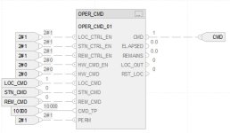
You can first look at the scratch of my AOI here:https://ibb.co/MMtxKnp


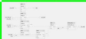
First you have the MOVE_BOOL AOI (bottom) that I created. If System EnableIn is true, it will pass the IN to the OUT. If disabled, it will stay in the last state.


At the top I have LOC/STN/REM_CMD as inputs, which represents BOOL commands coming either from three distincts HMI/SCADA. Up to now I'm trying to just have the LOC_CMD working, so the block isn't completed, I should have a reset and a MOVE_BOOL for each CTRL Authority.


So let say I have a Local HMI sending a command to LOC_CMD given that LOC_CTRL_EN is true, I'm gonna pulse the CMD Output for the CMD_TP duration (2.5 sec here). Most circuits are built that way: PLC output---2-3 second command to 24VDC relay----relay pulse into start / stop XV circuit in parallel of the start/stop buttons. This is why I don't latch.


After Timer.DN of 2.5 seconds, I want the block to force the LOC_CMD back to FALSE (so I could send the command again), so I pick RST_LOC, which should send a "0" to LOC_CMD by enabling the MOVE_BOOL block at the bottom.


But what is happening right now is that even if the MOVE_BOOL block is not enabled and LOC_CMD is "0", LOC_CMD still forces the input to stay false, which is a big difference with what I'm accustomed to with Unity Pro. This is why I added the MOVE_BOOL with the expectation that the scan order would take care of the issue after I have tried to manage it inside the block with the same result.


Does someone knows a way how I could reset that input to zero from within or with minimal effort? Or does someone have another idea on how to build that?


Thanks.
 
Not entirely sure what you want. But you can add pre and post scan routines. This may be what you are looking for
 
Not entirely sure what you want. But you can add pre and post scan routines. This may be what you are looking for


There is definitely something to be done with that, I'll dig into it.


What I want to do, simplified:


Input LOC_CMD comes from an HMI that set the bit to high. AOI executes and set the CMD Output to high for 2.5 seconds then back to low. It also needs to set the LOC_CMD input back to low so the HMI is also back to low and can re-initiate the same command.


Problem here is that having the LOC_CMD also written as an output forbid it to being set to high, even if my MOVE block is disabled.
 
Run an XIC LOC_CMD feeding a TOF loc2500ms_pulse 2500 0.

Replace the LOC_CMD on the input pin of your AOI with loc2500ms_pulse.DN.

loc2500ms_pulse is a timer object; make sure it's in a persistent scope.

The TOF will "stretch" the LOC_CMD single-scan pulse.

N.B. the TOF will restart the 2500ms if LOC_CMD becomes 1 while the TOF is timing; put an XIO loc2500ms_pulse.TT (or .DN) on the feed to the TOF input rung to prevent that.

Bottom line: many ways to skin this cat
 
Last edited:
Yeah, I understand that, but it's not how the HMI is working right now, I'd need to pulse the command from it, which I don't have.


LOC_CMD is a Modbus address being set to "1" by the HMI or SCADA. PLC needs to reset it on is own once the command has passed.


I need a way to reset LOC_CMD to "0" once the 2.5 seconds is done, so it also needs to be an output.


And since the LOC_CMD output is "0" at the beginning, I cannot even raise it as an input because the output is held by the MOVE block, even when the block is disabled. That was my way around with old versions of Unity Pro, output is kind of floating when a block isn't enabled and would just follow the lead instead of writing.


I'm looking for the loophole to make this work without rethinking the whole system.
 
If the hmi can write the 1, then the plc can write the 0. While it does not matter which of the two, HMI or PLC, writes the 0, having the plc do it is far more reliable; this pattern is called "set and forget."

Is the LOC_CMD bit used for anything else besides as an input to that oper_cmd AOI?

Is there anything besides the HMI that writes a 1 to the LOC_CMD bit?

Something is going to have to change, and it sounds like there needs to be an intermediate bit between either LOC_CMD and the AOI, or between the HMI and LOC_CMD, but that is not returning the whole system.
 
Thank you very much for your input, it's been too long since I worked with a Rockwell PLC and I'm lost.


Q: Is the LOC_CMD bit used for anything else besides as an input to that oper_cmd AOI?


A: Nope, it's only an input on the command block (read)


Q: Is there anything besides the HMI that writes a 1 to the LOC_CMD bit?


A: No.


Actually, I didn't set the comm yet so I'm toggling manually LOC_CMD and now I'm wondering if it messes with my test? I think I miss some basic knowledge of the Logix PLC.


Now I moved my logix from ladder to FBD to see if it would help, see attached screenshots. There is a couple of weird things in there.


I toggled the LOC_CMD to "1" on the "outside" input with the same name (could it be an issue that my tag has the same name as the input?).


Inside the AOI, LOC_CMD starts the TON even if LOC_CMD is at "0" from the MOVE AOI which is supposed to be disabled. Anyway*.


You can see that the output on the BAND is set to "1" even if LOC_CMD is "0", which is weird. That should be back to "0" and reset the TON.


Also, AOI's LOC_CMD is flickering to "1" once in a while. Looks like I cannot use that bool as an input and an output at the same time.


And, mostly, "outside" LOC_CMD remains to one even when the "inside" one is low.


Basically, what I'm looking for is to know how I can reset an "outside" bit from inside an AOI.

Sans titre.jpg Sans titre2.jpg
 
You need an OTU i.e. unlatch, so the HMI only can write a 1, and the PLC only can write a 0. But there is no OTU in FBD, so you will have to build the same functionality with an AND block that is evaluated after the TOF.
 
@drbitboy:


Actually, I managed to have it 90% working now in FBD.


I succeed in using an InOut parameter to reset the HMI command.


Unfortunately, the "toggling" of the command only succeed 75% of the time, probably because of the scanning order.


I'm trying to fix that now.


I've never spent that much time fixing such a simple issue.


Thanks for your time.
 
You are on Logix, right?

Even if you fix the scanning order, with Logix all I/O is asynchronous (I assume that includes HMI and online programming), so you don't know when the LOC_CMD bit will change to 1.

So if the code
(1) tests the LOC_CMD bit to take some action(s) e.g. start a timer and set the output bit value to 1, and
(2) then after that either tests it to clear it, or clears it unconditionally,​
it is possible that the value of LOC_CMD

  • could be 0 for the test in step (1) above, and
  • then change to 1 before step (2) executes, and
  • then cleared to 0 in step (2) above,
so changing the LOC_CMD value from 0 to 1, either by physical input, or by an HMI via some communication path (Ethernet/IP or DH+ or Modbus), or by Studio/RSLogix 5000 in online mode, could fail to cause the PLC to take the actions of step (1) above.

PLC programming is primarily about time, i.e. not so much managing what happens as when it happens.

So one thing I would do is never have the PLC clear the value of LOC_CMD to 0 unless the output value, which is triggered by a LOC_CMD value of 1, becomes 1. In your case, you could use the .TT or .DN bit of the TOF started by LOC_CMD as a proxy for that output.
 
Does this not do what you want, and perhaps a bit more simply and easily understood?

The values shown (1s and 0s) are for the edge case where the value of LOC_CMD transitions from 0 (TimerEnable input to TOF_01) before evaluation of TOFR_01, to 1 (In2 input to BAND_02) after evaluation of TOFR_01 but before evaluation of BAND_02, so the value of LOC_CMD being 1 will keep (latch) its own value (along with the value of NOT TOFR_01.DN being 1) until the next scan cycle, when LOC_CMD will start TOFR_01 to be timing, duting which timing TOFR_01.DN's value will be 1 so NOT TOFR_01.DN's value will be 0 so BAND_02 will then clear the value of LOC_CMD to 0.

I don't know if you want to go directly from the BAND_01 output to CMD or if you want to write the intermediate LOC_EXEC before the logic to write CMD's value, but that is a minor detail.
Sans titre2.png
 
I think that the best way to look for help is to publish what you have done inside the AOI together with the explanation, the figure is ok.
 

Similar Topics

Hi. Which of these system bits should I use to know that a particular AI or AO channel is faulted? Like I lost the 4-20mA loop, or the input is...
Replies
10
Views
881
Hi. Not the fist time I'm saying this but just to give a background. 95% of my PLC programming has used Schneider over the last 10 years on...
Replies
66
Views
4,998
So I have a question, How would I convert or transfer a program from Logix Designer to Rslogix 500. Im going to be taking said program and putting...
Replies
6
Views
1,615
Hello everyone! I am new to PLC programming and am using Studio 5000 to work with AB PLCs. My company uses VMware to allow me to remotely...
Replies
3
Views
1,325
All, Please help. I'm reaching the end of my rope with this thing... I can find tech notes galore on fatal errors with logix 5000 for everything...
Replies
7
Views
5,291
Back
Top Bottom