RSLogix / Logix Designer - Writing same value in an array

Watched this with a smile , Cannot believe the short sighted vision of RSL.
Many IDE's can have an array of timers with Time values stored in a variable
The code below shows a typical way of using a timer where the preset is a common variable not a fixed value & each timer can be referenced as an array of timers. So it is possible to either have a global variable for the PRE or even create an array of PRE & do a fill move so that all the timers PRE can be set to what ever time is required.
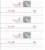
Timer Array.png
 
Wait.

Do you have one instance of an AOI evaluating logic on 16 boolean pairs (IN_xx and MASK.xx;xx=0-15), or sixteen instances of an AOI with each AOI instance evaluating logic on one boolean pair?

Because the latter might make more sense, two rungs (the OSR is unnecessary) in the AOI, and sixteen instances of (rungs with) that AOI.


(sorry, my first language is french, sometimes I get lost in translation)


So I'll rephrase it that way.


On a single AOI instance (all wired inputs will remap on that / those AOI(s) by groups of 16 representing half a module or a full 16 inputs module, don't remember if Rockwell has 64 inputs modules. Anyway.):


16 different inputs, with 16 different masks (INT.15 to INT.0) and timers (TOF[0] to TOF[15]), associated with 16 different outputs. I only showed the first IN/ OUT logic in message # 40, but there is 15 more of that after.


The ONR is necessary, it triggers the TOF to be on for 5 seconds as soon as the input is in (if alarm clears after 1 scan for example, it will stays on for "exactly" 5 seconds).


I don't want it to stay on 5 seconds after the input cleared if it already stayed on long enough (5s) for the HMI Modbus scan to pick it. Unless again I'm missing something in Rockwell philosophy.


(I know that 5 seconds is overkill but cause no harm because the _HMI tags are only for HMI/SCADA, I deal with control with the tags without _HMI. It's just a programming choice, we keep all logic in the PLC, no weird control / scaling / whatever in the screens, only annunciation and commands)
 
Last edited:
Watched this with a smile , Cannot believe the short sighted vision of RSL.
Many IDE's can have an array of timers with Time values stored in a variable


What is this one?


Looks like GE?


I showed the same thing using SE in message 12.


A lot of work to replicate in RSL, but now I know, thanks to people here.


18 more months of Rockwell with that project should help my understanding of it.
 
I don't want it to stay on 5 seconds after the input cleared if it already stayed on long enough (5s) for the HMI Modbus scan to pick it. Unless again I'm missing something in Rockwell philosophy.


So if the input stays on for 10s, you want the output to be 1 for the first 5s of those 10s, and then you want the output to be 0 for the second 5s of those 10s?
 
It's mitsubishi, done in FBD but the timers in the older ladder version will work the same, you can have a global variable for the timer presets, you can also indirectly address timers using the index register.
 
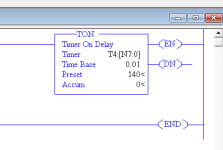
It does not appear to be.

The preset and accumulator do not resolve, and when verifying you get missing operand errors for them.


A hack workaround could be implemented e.g. use an INT array arr[15]:
BST  XIC INP[xx] XIO OUT[xx] NXB GRT arr[xx] 0 BND OTE OUT[xx] ADD arr[xx] 1 arr[xx] AND arr[xx] 0FFFh arr[xx]


When INP[xx] transitions from 0 to 1, this will put a 1 in OUT[xx] for 4096 scans, which might be around 5s.
 
So if the input stays on for 10s, you want the output to be 1 for the first 5s of those 10s, and then you want the output to be 0 for the second 5s of those 10s?


Nope, see next message.


INXX is connected directly on OUTXX too, not only on the RTRIG, so if INXX is high for 3 months, alarm will be on for 3 months.


But if INXX comes in & out inside 5 seconds, it will stay on for minimally 5 seconds.


And if INXX cycle each seconds, TOF will also make sure that the alarm isn't cycling on operator screen, it will stay on. It will start to be annoying to the operator if it cycles every 6 seconds and more.
 
Last edited:
Another question would be...


Why do we need 2 tags to create a OSR?


What is the purpose of the Storage Bit?

The storage bit allows the instruction to tell whether the rung has just become true, or has previously been true. It is needed to have the output bit used as a separate XIC.

If you want a oneshot that uses only one bit, use ONS. In exchange for using less memory you sacrifice the ability to check it on multiple rungs. I frequently use bit-addressed DINT for in ONS for oneshots.
 
It's looking better now but I just don't understand why _APS_F_HMI is showing "0" when OUT_02 is showing "1".


Found the problem.


Pending edits since then.


That is messed up since I did a full download about 10 times since that "uncompleted edit".


Another particularity I wasn't aware of.
 
The storage bit allows the instruction to tell whether the rung has just become true, or has previously been true. It is needed to have the output bit used as a separate XIC.

If you want a oneshot that uses only one bit, use ONS. In exchange for using less memory you sacrifice the ability to check it on multiple rungs. I frequently use bit-addressed DINT for in ONS for oneshots.


Great. Thanks for the explanation!
 
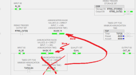
Here.


After 8 seconds, TOF.DN is now false even if "masked",


... because the logic propagating from TOF[0].DN to OUT_00 is masked, but the logic propagating from INP_00 to the TOF instruction using TOF[0] is not masked.

Axiom: the PLC cares not a whit what you want or expect it to do, but is will mercilessly and inexorably do exactly what you tell it to do.

Corollary: the only thing worse than the PLC not doing what you want it to do is when it does exactly what you told it to do.

but OUT is still true since IN is still true.

Try this instead:

  • Rung 3: the mask value, if 0, prevents the TOF from starting to time, which also prevents TOF[0].DN from becoming 1.
  • Rung 4, top branch: the mask value, if 1 (XIO 1 => False), prevents the value of IN_00 from triggering the OTE to write a value of 1 into OUT_00
  • Rung 4, bottom branch: TOF[0].DN does not need to be in series (ANDed) with the mask value, because TOF[0].DN is already effectively masked on Rung 3 (above).
Sans_titre.png
 
  • Rung 3: the mask value, if 0, prevents the TOF from starting to time, which also prevents TOF[0].DN from becoming 1. I agree with that, it's a better location. I don't think it was harmful where is was, but that's good practice indeed, I missed it.
  • Rung 4, top branch: the mask value, if 1 (XIO 1 => False), prevents the value of IN_00 from triggering the OTE to write a value of 1 into OUT_00 There may be a misunderstanding here. I want it (OUTXX) to be high whenever INXX is High. Like you drawn it, it would kill a "masked" alarm after 5 (or 8) seconds if alarm stays on longer than that. What I want to do is only to make sure that the alarm stays ON for a minimum time in the case it reset by itself before 5 seconds. Maybe the "mask" terminology is not appropriate for what I want to do with it.
  • Rung 4, bottom branch: TOF[0].DN does not need to be in series (ANDed) with the mask value, because TOF[0].DN is already effectively masked on Rung 3 (above). Yes.
 
It does not appear to be.

The preset and accumulator do not resolve, and when verifying you get missing operand errors for them.


This verified fine for me, RSL5 v8.0, no errors or warnings


Plus the previous post that looks like SiemensLOGO shows what I suggested before, the timer PRE is an integer tag - so it can't be impossible

Capture.PNG
 

Similar Topics

Hi. Which of these system bits should I use to know that a particular AI or AO channel is faulted? Like I lost the 4-20mA loop, or the input is...
Replies
10
Views
880
Hi. I'll say it again, I worked mostly with Unity Pro for the last 12 years and I'm trying to convert our FBD standard to Rockwell Logix...
Replies
13
Views
1,507
So I have a question, How would I convert or transfer a program from Logix Designer to Rslogix 500. Im going to be taking said program and putting...
Replies
6
Views
1,615
Hello everyone! I am new to PLC programming and am using Studio 5000 to work with AB PLCs. My company uses VMware to allow me to remotely...
Replies
3
Views
1,325
All, Please help. I'm reaching the end of my rope with this thing... I can find tech notes galore on fatal errors with logix 5000 for everything...
Replies
7
Views
5,288
Back
Top Bottom