Siemens S7/TIA v16: What memory address should I use for a pushbutton on the HMI?...

Mas01

Member
Join Date
Oct 2020
Location
Leicester, England
Posts
1,109
Sorry for the basic question:

On my HMI, I've created a button labelled SAVE to save the current values (distances in mm). It's not linked to any Boolean in the code yet.
When the screen button SAVE is pressed, the values of certain tags are saved.

Basic question: What's the best way to define this Boolean in terms of its address? Am I free to call it M0.0 in the code or should I call it something else?

EDIT: I think I heard something like using M-bits was not good practice?
Hope that makes sense. Thanks
 
Last edited:
There is no problem using M bits but do not use M0.0 to M1.7 as these are often used for special bits *(configured in the setup). Also, not sure on TIA but on the older platforms MW200 to 255 (16 bit words i.e. M200.0 - M255.7) were used by Siemens own special FB's probably not the case now.
I assume you are using a DB to store the values again not used S7 for a number of years but there is probably a standard block to do a block transfer i.e.

I think it's called BLK_MOV
Parameter Declaration Data Type Memory
Area
Description
SRCBLK INPUT ANY I, Q, M, D, L Specifies the memory area to be copied (source
area). Arrays of the data type STRING are not
permitted.
RET_VAL OUTPUT INT I, Q, M, D, L If an error occurs when the function is being
executed, the return value contains an error code.
DSTBLK OUTPUT ANY I, Q, M, D, L Specifies the memory area to which the data will be
copied (destination area). Arrays of the data type
STRING are not permitted.
 
Cheers parky - I will steer clear of M0.0 to M1.7, thanks for the info... perhaps I'll call it a nice round number like M10.0, something like that.

And, yes, I'm defining a Data Block to define the saved values, so they are retained after PLC reset.
 
What is the reason for saving them are they some form or recipe or is it a kind of logging function or just as a backup ?.
I noticed you have a post about some laser systems is it to save this data ? are these read or written to It really depends on what this data is for.
 
What is the reason for saving them are they some form or recipe or is it a kind of logging function or just as a backup ?.
I noticed you have a post about some laser systems is it to save this data ? are these read or written to It really depends on what this data is for.
Yes, it's for saving the laser measurements.
Laser is this one:
https://www.micro-epsilon.co.uk/displacement-position-sensors/laser-sensor/optoNCDT_1220/

Basically, we've got a series of Laser sensors around the profile of a machined component.
We have a "master" component which has the "ideal" dimensions...this one's locked away and handled with kid gloves.

These lasers measure the distance between the laser head and the profile of the master component.

These measured values (mm) are to be SAVED in the PLC.

Then, that master component is removed, and in its place goes a 'freshly-made-in-the-factory' component (It's anchored in the same place as the master component with some sort of lock nuts).

Again, the laser measurements are taken.

Then we subtract the new values from the saved values.

If the differences are within a specified tolerance, the new component is PASS and goes for shipping. If it's FAIL it needs rework.
 
Last edited:
Ah.. so it's measured, then stored for retrieval so there is only need for one set of measurements then very simple If you make sure the DB tags are the same as the ones you are copying & the DB is the same size remembering that the tag type needs to be the same type, Data tags in the DB can be configured as most types i.e. integer, double, float (real) as datawords are in bytes you will notice that it starts at 0 then if configured as a byte then the next tage will be 1, however, if it is an integer it goes up in two's i.e. 0, 2, 4 a float will take 4 bytes (8 bytes if a double precision) etc. very much like Mitsi where a double or a float takes up two words (4 bytes).
 
Sorry for the basic question:

On my HMI, I've created a button labelled SAVE to save the current values (distances in mm). It's not linked to any Boolean in the code yet.
When the screen button SAVE is pressed, the values of certain tags are saved.


The PLC has Recipe instructions that can help with that, by the way. They write to the memory card, so that you don't have to worry about accidentally overwriting the remnant values in the DB at the next reinitialization.


Basic question: What's the best way to define this Boolean in terms of its address? Am I free to call it M0.0 in the code or should I call it something else?


The best practice is to use the tag's name in the code, not it's address.


EDIT: I think I heard something like using M-bits was not good practice?
Hope that makes sense. Thanks


M bits have no inherent structure, and therefore don't allow you to use most of the modern programming methods (like UDTs). There are also many ways to get yourself in trouble (like accidentally declaring an int as MW14 after using M14.0 as a bool). They WORK, but they are a hold over from legacy systems mostly there for backwards compatibility reasons. There's nothing WRONG with using them, but it isn't the best practice.
 
The best practice is to use the tag's name in the code, not its address.

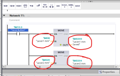
Cheers, but I don't understand this.
When I've been writing code, the memory and tag name have gone hand-in-hand - see the pic.
Or maybe I misunderstand you.

e mem address and tag name.png
 
Last edited:
Note that MD8 occupies MB8,9,10,11 so your M10.0 will not behave as expected. Ditch the M flags and use data blocks.
 
Again, not an expert on TIA but on some systems HMI's can only access tags that have a real address, not so for CLX as they are purely tag based.
So if you need an HMI to access a variable then configure the address & give it a symbol. symbol only use, the actual address in memory is allocated at compile time on many systems so not known by the HMI.
As people have already posted especially for int/words/floats etc. use a DB.
It also makes sense if you use VAT tables for monitoring it can be difficult to remember the exact symbol name & add that to it but by putting in the DBx.x it will display the symbol just like when you are writing the program.
Also when adding a variable in some code usually, typing in the first couple of letters of a symbol will bring up a list of them so you just select them.
There is a trend to go away from pre-fixed addresses to symbol only, but I'm not sure siemens HMI's can read those at this time perhaps others here could enlighten us.

I missed this while I was posting the last couple of messages.
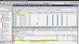
Yes - DBx.x is exactly the format that shows in the code.
Many thanks.

G x dot Y DB table ref.png
 
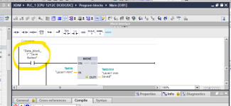
you need to show a bit more code, it is difficult to see what you are trying to do but to start with it is not usual to write the code in OB1, you create a program block FC (or is it an FB) so long I cannot remember, there you write the code & call it in OB1, you split the program into manageable sections like:
FC1 Analogues
FC2 Digital input map
FC3 Digital output map.
FC4 Laser Data manipulation
FC5 Motor calls
FC6 Valve calls
FC7 Main sequence program
& so on
Then call those blocks in OB1 either unconditionally or conditionally if they only need to run when certain logic is required.
TIA like Mitsi (GXWorks), AB, etc. are designed for structured programming so rather than have one big block of code you split it into different programs.
It also makes sense that if you have motors or valves etc. to create functions like motor or valve control, these are only written once then you call them many times passing information to them the block will have input & output parameters so everytime you call the block you populate it with the relevant signals for that valve, this way you only write the code once but call it many times.
See pic of a structured program

Structured.jpg
 

Similar Topics

In OB1, I'm monitoring some values (first pic). The values are what I expect. At the same time, I'm monitoring the same values in the DB where...
Replies
1
Views
651
Siemens S7/TIA v16: "Overwrite if object exists online?" HMI loading message... Thus far, I've just been ticking this box, just to get the HMI...
Replies
4
Views
769
I'm having a bad day. Daft question coming up...Anyone know why I can't add anything into this DB? Add button is greyed-out. Thanks
Replies
14
Views
1,597
I imported a customised shape into the project, but I don't know how to actually add into on to a specific HMI screen. Do I use the Graphics menu...
Replies
2
Views
661
Hi I'm trying to display a value on the HMI. In monitor mode on the code, I can see that value, but on the HMI , after downloading, it is...
Replies
10
Views
947
Back
Top Bottom