Speed control using level switches

AutoWorks

Lifetime Supporting Member
Join Date
Jun 2016
Location
Cincinnati
Posts
10
Anyone have a plc program example of speed control on a vfd using high/low level switches. Speed increases for every second the low level is on, slows down for every second the high level is on or some variation of time. Looking for it to be somewhat stable operation without too much hunting. (excessive speeing up/slowing down).
I'm using RSLogix 5000 but any plc software example would be great to see.
Thanks in advanced.
 
I don't have an example, but you should be able to muddle through this with a little thinking.

Why don't you take a shot at it and post your work?
 
The only way I can see to make this work is if you know roughly what the flow in and out of the tank is. You would then have to set the drive for the expected flow and use the high/low limits to deal with flow rates outside of the expected. Even then, you won't be able to maintain a set level in the tank. With this setup, the best you can hope for is the tank doesn't overflow, or go empty. Neither is guaranteed however.

Bubba
 
It sounds like a discrete I-only feedback control.

The behavior I would expect is, for example, if the low level input is 1, indicating a low level, then the controlled inlet flow will increase as long as that low level input is 1, and that low level input will not change to 0 until the controlled inlet flow exceeds the outlet flow i.e. so the level rises, and it will eventually hit the high level and the opposite will occur, so it's always pillar to post i.e. hunting.

Even if the controller inlet flow exactly matched the process outlet flow at some point, it could only reach that point during a period with a high or low level input as 1, so the inlet would never stay there.

Basically this is the same as a reset windup problem in a PID.

I wonder if the behavior could be characterized e.g. the time spent with either level input at 1 could be used to characterize the outlet flow, or more specifically the difference between the inlet and outlet flow as a fraction of the inlet flow, and use that to estimate inlet flow should be to balance.

It's a reasonably linear process, so this should be easy to model.
 
Last edited:
To parabolas, and beyond!

Summary

As it is described in the OP, this method is not likely to work very well

To zeroth order the inlet flow will cycle indefinitely between constant offsets above and below the outlet flow, and the level will cycle between constant offsets above the high level and below the low level.

Caveat

The modeling below uses a constant outlet flowrate

Details

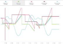
I think the plots in the image below, describing the behavior around a low-level event, represent a simple, but reasonable, model, for the process and feedback control described in the OP. N.B. after the sixth second, the net (outlet - inlet) flow rate will be +3gal/s, so the tank volume will increase to the High Level Trigger Point at that rate, and then execute similar behavior to the plots in reverse.

To first order, considering actual dynamics, such as hysteresis in the level switches and temporal transients between inlet flow setpoint and actual values, the offsets between which it cycles may increase, both in flow and in level.

That said, it does look like giving back half of the change in flow rate change applied during any level event, once that level was recovered, would have a decent chance of setting inlet flowrate near the outlet flowrate.

xxx.png

Although shown in discrete form here, for the continuous process, which a PLC running scans at order 1kHz would approximate, the governing first-order differential equations:

  • dVolume/dt = Flow
  • dFlow/dt = ±Constant
  • Flow(t) = Flow(t=0) ± (Constant * t)
  • Volume(t) = Volume(t=0) + (Flow(t=0) * t) ± ((Constant * t**2) / 2)
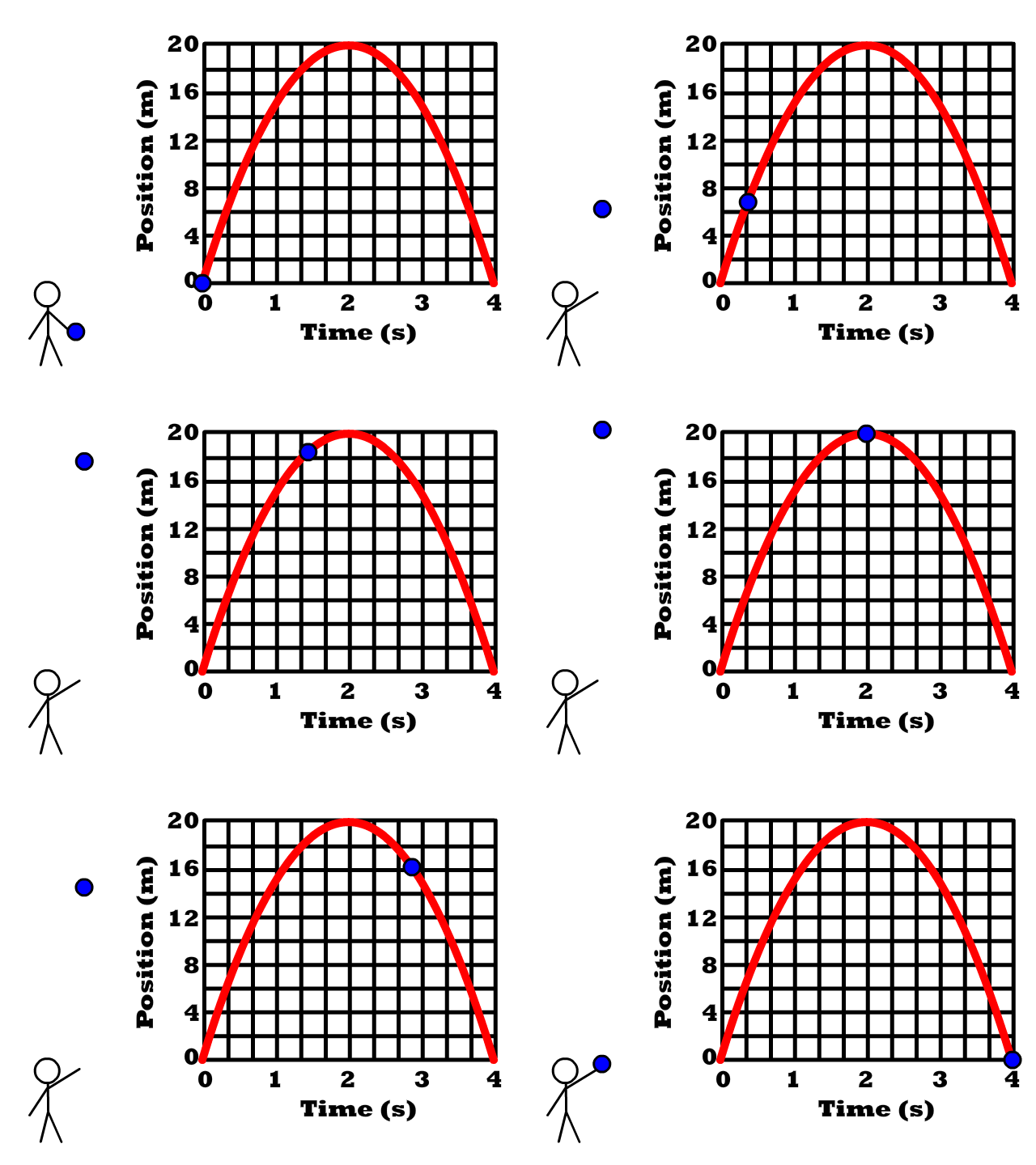
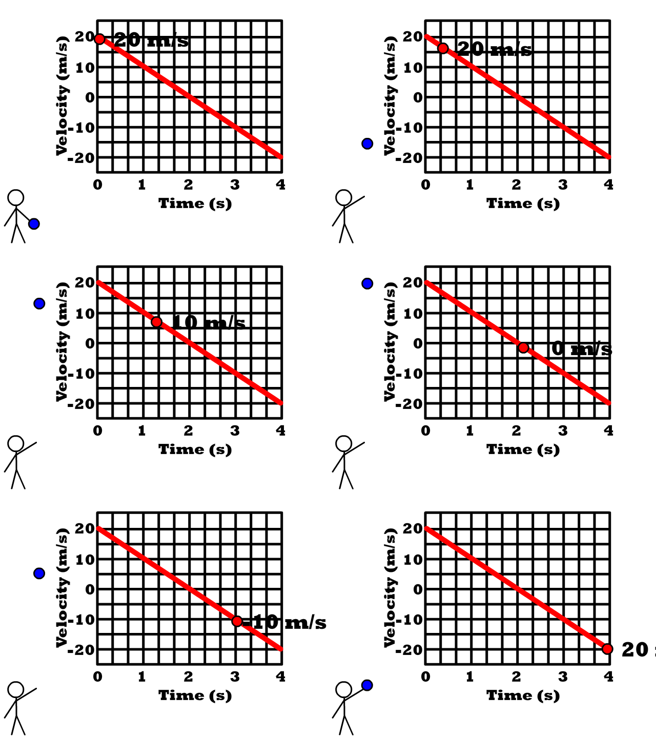
are the same as the height of a ball thrown upward and acted on by a constant gravitational acceleration:

  • dHeight/dt = Velocity
  • dVelocity/dt = Constant Acceleration = -g
  • Velocity(t) = Velocity(t=0) - (g * t)
  • Height(t) = Height(t=0) + Velocity(t=0) * t) - ((g * t**2) / 2)
I.e. the profiles of both Height and Volume over time are parabolas.

PG12C1_007.png

Cf. https://cnx.org/contents/udH40vG5@2/Motion-in-Two-Dimensions-Grade-12


PT-Graph-Gravity-Ball-Thrown-Up.gif
VT-Graph-Gravity-Ball-Thrown-Up.gif
Cf. https://stickmanphysics.com/stickma...mensional-motion/acceleration-due-to-gravity/
 
Last edited:
I've always just used the Electronic Pot, or Motor Operated Pot (MOP) function on the drives, such as when controlling duct pressure using a Photohelic. The Accel/Decel rates effectively act as the Integral Time.
 
Regardless of the informed complicated replies, I would add this to your speed control alogorithm....

I will assume, from your description in the OP, that you are filling a vessel.

When you hit below low-level, don't ramp the filling pump speed up, but step it up to 100%. Drop it back down to 50% if the low-level becomes covered again after an adjustable time delay. Alarm if the low-level does not get covered in xxx time, because you are starving the processes using the fluid, whatever it is.

Same goes for high-level, drop the filling pump speed to 0%, and when the high level becomes uncovered, wait an adjustable time delay before putting the pump speed back to 50%. No alarm needed, the process is not using anything ... However, the "below low-level" situation should override any delays on filling.

Since you have no level monitoring in place, and are purely relying on High and Low level switches, you absolutely WILL get hunting, but with suitable time delays, and "mid-level" speeds the hunting can be reduced in severity, but never eliminated.

I can see no need at all for ramping, the targets are fixed, so hunt between them.
 
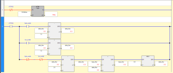
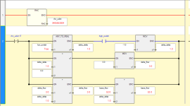
At a mere dozen instructions, it does work as predicted for simple step perturbations, with the parabolas and the factor of two 'n'all. It will take some tuning to set the [delta flow per second] to control the excursions, but that is expected.


I agree with @daba though i.e. I don't see the point.


discrete_in_analog_out_logic.png

discrete_in_analog_out_trend.png
 
Best off-the-top-of-my-head solution

Your "hunting" is a game of ping pong between the two limit switches.

To get around that, capture the VFD speed as soon as you hit the low switch (SPEED_TOO_HIGH) and when you hit the high switch (SPEED_TOO_LOW). Rather than incrementing the speed, ramp the speed from where it is now to the average of the two, then hold there:
XIO(TON.DN) CPT[VFD.SpeedReference = SPEED_TOO_LOW + (TON.ACC/TON.PRE)*(AVE_SPEED - SPEED_TOO_LOW) ];
XIC(TON.DN) MOV(AVE_SPEED VFD.SpeedReference).

The basic problem is that, by incrementing the VFD speed while it was too low, you've essentially wound up an integral term on an invisible PID (error * time), which had no way of correcting while the "error" (desired speed minus actual speed), was gradually reducing because you have now way to know what the "desired speed" is. So, we guestimate where that I term was going to take us (midpoint between low and high).

The ramp isn't strictly necessary, perhaps, but if you hit the low switch during the ramp, then clearly SPEED_TOO_HIGH was initially too high, and the current ramped speed makes a better starting point than the old AVE_SPEED had you merely set the speed to the midpoint.

You can get more creative with this: if you hit and leave the low switch twice in succession without hitting the high switch, then that midpoint between high and low isn't the equilibrium point. So artificially add X to the high speed capture to move the average point up. Similarly, subtract Y from the low speed capture.

Perhaps AVE_SPEED isn't a midpoint, but a non-linear calculation based on the pump curve.


With luck, the only time you'll hit the switches is if the process dynamics change (increase in tank consumption). When that happens, the new "sweet spot" will get calculated, and with even more luck (and perhaps one or two more switch hits) will serve until the next dynamic change.

That's really the question: how much does the process change? If frequently, then daba's solution may be better: don't worry about hitting a "sweet spot", just ensure that there's enough volume in the tank serve the rest of the process. If hiccups are rare, then perhaps this solution (which is akin to drbitboy's parabola thing) will work better than what you have now.
 
Your "hunting" is a game of ping pong between the two limit switches.

To get around that, capture the VFD speed as soon as you hit the low switch (SPEED_TOO_HIGH) and when you hit the high switch (SPEED_TOO_LOW).

Close, but the right thing to do is to take the average of the two speeds at the transitions of the same switch at either end of a limit excursions e.g.

  1. when the low switch has a 0-to-1 transition (SPEED_TOO_HIGH), and
  2. when the low switch has its next 1-to-0 transition (SPEED_TO LOW).
And the same for the high switch excursions. This assumes

  • a constant flowrate ramp whenever one of the switches is a 1, so hopefully the speed is on a reasonable linear section of the speed vs. flow curve.
  • a constant process flow
Those are weak assumptions, of course, but they are the only practical ones available; another non-linearity is the hysteresis of the level switches. But if those assumptions are roughly correct and the hysteresis is a small fraction of the events' durations, then that will minimize high- and low-level excursions.
The basic problem is that, by incrementing the VFD speed while it was too low, you've essentially wound up an integral term on an invisible PID (error * time), which had no way of correcting while the "error" (desired speed minus actual speed), was gradually reducing because you have [no] way to know what the "desired speed" is.
Exactly. However, without knowing the actual pumped flowrate to divide into the volume between the level switches, the time between the the end of a low event and the start of a high event is meaningless, and therefore so are the speed values at those events.

The only way to estimate the difference between SPEED_TOO_LOW and the speed-equivalent of the process flow is with the ramp and the assumptions of linearity.
 
Last edited:

Similar Topics

I am at a loss... I have a pasteurizing system that i need to control product temperature with the speed of the product pump. I currently have a...
Replies
11
Views
2,600
Hello All, I have two bags of two different types of peanuts hanging on a load cell above two separate feeders. I am using Studio 5000 and would...
Replies
45
Views
8,852
S7-315 I have inherited a job that someone else designed and started. It has Hydraulic Servos 0-10v from an analog OP card and Encoders back to an...
Replies
9
Views
2,241
Hi i want to control the speed of AC drive using Another Drive reference output . please help me :bawling: And also i am confused in practical...
Replies
2
Views
2,074
Hi All!!! It's my first post on this forum so be a patient,please. I'm writing program using RS Logic 5000 and I need have a variable speed...
Replies
19
Views
8,527
Back
Top Bottom