tia portal v14 modbus

RY_Guthrie

Member
Join Date
Nov 2011
Location
Las vegas, NV
Posts
263
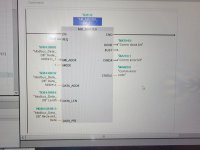
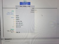
I am beatin gmy head against the wall trying to get my modbus comms working. I have a s7-1200 running tia v14, a cm-1241 comm card. I have attached the modbus load and modbus rtu setting FB's. the modbus load is in the startup routine, ob100 and the modbus rtu setting is in the fc1 routine. I am not getting the tx rx lights on the card at all so its like its not even trying to communicate. I am going to try a modbus simulator today to see it either the master or the slave is not working.modbus comm load.jpg
modbus master.jpg
 
On the MB_COMM_LOAD you havent assigned a variable to STATUS.

I dont know the modbus blocks, but I am pretty sure you cannot simply have a constant TRUE on the REQ input.
The block probably needs a rising edge on the REQ input.
My guess is that you must combine with DONE, ERROR and STATUS to generate the rising edge.
Do you have a sample project to start out with ?

When you get that far, and it still wont work, then use the STATUS outputs to get diagnostics.
 
lunenburger, I just notice that your MB_COMM_LOAD is different to RY_Guthrie's.
Different library blocks ?

Sometimes there are different blocks for S7-1200 and S7-1500, but you are both using S7-1200 so that is not the explanation.

A sidenote:
There is a function to hide/show unassigned IO pins. I wondered if that could be the reason for the different blocks, but since ERROR and STATUS are not assigned in RY_Guthrie's block and they still show, I guess that is not the explanation.
 
Just for completeness sake...

Re the "hidden IO parameter".
When you have a hidden unassigned IO parameter, there will be a small arrow at the bottom of the block. Clicking the arrow will display the hidden parameters.
luneburgers MB_COMM_LOAD block actually show such an arrow for hidden parameters, but RY_Guthrie's does not.
 
The manual says you have to use the first scan bit on the comm load.

I have attached a pic of the setup for my modbus setup to a Vacon drive with S7-1200 PLC.


I have attached a link to the video that helped me alot to set up the communications

https://www.youtube.com/watch?v=1fMaw6GATws
it is in the mb comm load is in the start up block and if i understand that correctly it scans it once at start up?
 
it is in the mb comm load is in the start up block and if i understand that correctly it scans it once at start up?
That wont work. The modbus blocks are 'asyncronous' blocks, which is another way of saying the must be executed over several PLC cycles. Just one cycle such as in the startup OB is not enough.

That is why there is a DONE bit on both blocks. I am guessing (because I am not familiar with these blocks) that you need to run the MB_COMM_LOAD block at least until DONE is set.
Also on lunenburger's version of the MB_COMM_LOAD block there is a REQ input. How should the MB_COMM_LOAD block be able to detect a rising edge on this pin if it only were to run in one scan ?
 
The "Modbus_Comm_Load" block is used to select the communication module, set
the communication parameters and parameterize the connection with the master or slave parameters.
The "Modbus_Comm_Load" block must be called in the first program cycle (by activating the "Initial
Call" of a cyclic OB, for example, or as a call in Startup OB 100). After inserting the
communication module in the hardware configuration you can select the symbolic name of the
communication module at the PORT parameter. The communication parameters BAUD (transmission rate)
and PARITY (parity) must be identical for all nodes. The port configuration of the RS485 interface
in the STEP 7 (TIA Portal) device view is irrelevant here. The "MB_DB" parameter of the instance
data block of the master or slave block is transferred at the MB_DB parameter and thus defines the
communication module (PORT parameter) as MODBUS master or slave.
In addition, you must change the static parameter MODE in the instance data of the
"Modbus_Comm_Load" for the duplex operating mode, preferably via the start value (0 = full duplex
(RS232), 1 = full duplex (RS422) four-wire mode, 4 = half duplex (RS485) two-wire mode).
this is directly from the Siemens manual. it says it can be in the start up block, OB100?
 
I’ve always gotten my simulator working first. Then tackled the plc part

And used the simulator to talk to the plc

Sounds like your not positive you can get data from your device yet
 
Last edited:
this is directly from the Siemens manual. it says it can be in the start up block, OB100?
I can see that it does. Makes no sense to me, or is it guaranteed that DONE is always set ?
If DONE does not get set, what is one supposed to do, if the block is only called once in the startup OB ?

When I add a MB_COMM_LOAD, there is also a REQ pin, like in lunenburgers example.
The same argument for the REQ pin, the block needs to see a rising edge, and that is essentially impossible with a single call in the startup OB.
This is what it says in TIA online help for MB_COMM_LOAD and the REQ pin:
Starts the instruction upon a positive edge of this input.
I cannot find anything that says that the block is to be called only once.

Somehow, I think you are using some other blocks. I find the modbus RTU blocks under the extended instructions, .. Communication processor .. MODBUS (RTU).
Do you also have the blocks from there ?
You are using a CM1241 for the modbus RTU comms ?
 
ok, I added the status and error code tags to my mb_comm_load and I get error code 8180 on first scan, invalid value for the port ID (wrong address for the communications module) I also get this same error on the modbus master, 8180. But for the life of me I dont know where I am supposed to set, get or read that address from?? Excuse my ignorance, i inherited this program, I did not create it, it was written by someone else and I am not privy to there thought process.
 
Notice that on the PORT pin there is placed a system constant called "CM1241_(RS422_RS485)_1" and which has the value 278.


Open the device configuration.
Select the CM1241 module.
Then open the "system constants" (or is it "system texts", dont remember now).

Is there a system text with the same name and value as described above ?
 
went to device configuration, my cm_1241 (rs422/485)_1 module and system constants and its blank. Which in my little mind isnt correct as I compared it to the cm-1242 card right next to it and there tags associated with it. I cant thank you enough for taking time out of your life to help me, siemens is not my strong point, I am a Rockwell guy, and they are as different as night and day!
 

Similar Topics

Hi everyone. Please help me to upload program from S7-1200 with TIA v14. I created new project, go to Online tab, select Upload devices as new...
Replies
0
Views
1,084
I am trying to commission a compressor that is using a s7-1200 to communicate rs485/modbus to a the compressor interface. My rs485 module is a...
Replies
2
Views
1,700
Is it possible to install Siemens Tia Portal V14 on a machine that already has V16 installed? Or do I need to create a virtual machine to install...
Replies
17
Views
8,896
Is anyone know how to change the state of Button and multistate indicator(for Verify changing in color and text) in TIA portal HMI while doing...
Replies
1
Views
1,323
Hi all, I'm working on migrating some old Sinamics S120 drive units currently integrated in Step 7 5.6/WinCC Flexible 2008 RT to TIA Portal V14...
Replies
7
Views
3,394
Back
Top Bottom