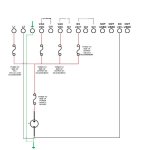
Used Micro Logix 1000 trainer used

Gentleman
I really wish to relay (no pun intended) on to all those that helped me with this problem I was having with the trainer I built, a real sincere thanks for your time and insight to help me. I feel a real sense of thanks to you all. But doing the build myself gave me a chance to plan and build which I cherish

I have found the problem
I kind of feel like a dumbbell, but that is all a part of learning I guess.
the problem was that terminal 13 DC 24V- needed to be grounded. I ran a wire to the Terminal 2 the - of the 24VDC IN and it came to life. I hope you all can use this as part of your knowledge base to teach other dumbbells like me in the future.

Bering, thank you for the drawings, Allen Bradley does not make things easy to get. the manual was a great find. I asked for simple amp draw info from AB and got a run around
What tripped me up is the why they labeled the 0/0 and 0/1 outputs and the 0/2 and 0/3 another way. Also I was thinking that was a negative 24VDC.

warm regards to all
David
 
Last edited:
The problem was that terminal 13 DC 24V- needed to be grounded. I ran a wire to the Terminal 2 the - of the 24VDC IN and it came to life.
Just for your future use, technically what you added was not a "ground" as such. It is simply the negative side of the circuit for your PLC. All circuits must form a complete current loop, and you only had the + side wired. If all you had added was the "ground" wire from an earth ground to the L2 terminal ("grounding the - side of the power supply), but did not add the - wire to the -24 VDC PLC terminal 13, then your circuits would still not work.

If you do have the - side also connected to the PLC earth ground point, then you can now call the -24Volt lines "grounded" also, but the grounding of the - side of the circuit is optional for 24 volt circuits.
 
Last edited:
I kind of feel like a dumbbell, but that is all a part of learning I guess.

Welcome to the wonderful world of automation, we all over look things from time to time

I do a lot of troubleshooting over the phone and I learned that looking at the basics are the best place to start, a couple weeks ago I was helping one customer... 30 min into the conversation I decided to ask if the power was on to the machine, once he turned on the power we were able to get communication with the PLC :)

Ron I would of thought you were no older then 39 :)
 
I meant the fact that someone in today's "that's-close-enough" world actually CARED enough to go back and "fix" something that they could have simply just let "slide" ...

there aren't enough people around today who CARE anymore ...

I'm 68 years old - and I can easily see the difference in the attitudes that people (in all walks of life) have toward the quality of the work that they do ... things have changed over my lifetime – and not for the better ...

I am always amazed - and appreciative - when I come across someone who actually DOES seem to care – and who is willing to put forth an extra amount of effort to get a job done "right" ...

These day's we're mostly just labelled "anal-retentive perfectionists". But we still exist ;)
 
Would the 1761 L10 BXB be safe if i up the 1amp fuse to a two amp fuse
All my other outputs are four LEDs
I wany to use an electric 3v motor that will draw .28a running and .47a when starting
I look at manual again but a bit unsure yet
 
I would have separate power supplies, I dont like DC motors running on anything but themselves...
 
Also you may be better off fusing your outputs separate from your PLC protection.

Each group of outputs can be fused separately or you can combine certain groups and fuse other by themselves. (what ever combination works for what you are doing)

This way you protect your power supply, plc, and each group of outputs at their correct individual current rating.

(Just be sure to read the manual and dont oversize the fuse for each group of outputs.)

If you use 2 power supplies as Mark suggested then same principal will apply but you will feed and fuse your motor output from the additional power source.


See pic below:

OUTPUT FUSED JPEG.jpg
 
3v motor

Its just a little motor about the size of a Iphone usb charging outlet
is 2amps too high? to protect the PLC?
 
is 2amps too high? to protect the PLC?
According to the MicroLogix 1000 Installation manual, page 22, the 1761-L61BXB uses 5 watts at 24 Volts DC, or 5/24 Amps (0.208 Amps). So a 1 Amp fuse would probably work if that is the only device on that fuse, and you use a separate fuse for your Output power.

The internal MicroLogix power supply has a maximum in-rush current of 30 Amps for 4 milliseconds, so you should use a "slow" fuse that does not trip in 4 milliseconds.

There is a chart showing the maximum currents for the 2 types of outputs on this PLC, the 2 MOSFET transistor outputs, and the 2 relay outputs on Page 25 of the Installation Manual. Summarizing, the MOSFET transistor outputs will safely handle about 1 Amp each. The relay outputs for make-and break of the contacts can handle 1.2 Amps each at 24 VDC, or up to 2 Amperes steady-state current. At higher (120 and 240 VAC) voltages, the relays can pass 2.5 Amps. Bottom line: assume you can only load each of the 4 outputs at the 1-Amp level.

Your Output fuse should be based on the total summed loads on all 4 outputs, plus a small margin for error. If you only use 1 fuse for the PLC and the Outputs, then you must add the 0.208 Amps to the Amp Output load and try to find the smallest fuse that will not burn out at the maximum expected load.

For your motor, I would add an interposing relay that is operated by a PLC output, then run the motor off of the interposing relay contact. That will eliminate any possibility of burning out your PLC output. Your stated maximum 0.47 starting Amps should be okay to run directly on one of the relay outputs, but things rarely go as planned.
 
Last edited:

Similar Topics

I went on a service call yesterday for a Micrologix 1500. An output wasn't activating and they wanted to know what was hanging it up. It was a...
Replies
10
Views
2,808
I program with very basic operations, more like a shift register type seqeuntial format by just latching rungs etc. as program progresses. I never...
Replies
2
Views
3,521
Hi, I've come across a customer using IDEC Micro-1. FC1A-E1A1 & FC1A-C1A1 (Expansion unit). If not mistaken this Micro-1 is an obsolete model...
Replies
9
Views
7,401
hi all i am new here i have a mitsubishi smart touch hmi i.e ms-60t-pe but i cannot find a software to edit and download a program in it any help...
Replies
3
Views
163
FactoryTalk View ME running on PanelView Plus 7, connected to Compact GuardLogix 5380 PLC Customer is asking for a physical push button to be...
Replies
6
Views
182
Back
Top Bottom