Used Micro Logix 1000 trainer used

Is the wiring different? all ouputs wired the same
Is the power supply the same? Same power supply
Are the LEDs the same brand, model, and size? all opperate at 2-3 V, I took a separate 24VDC source and all LEDs lit when I touched the wire to their path
Do you have the 3 unlighted LEDs turned the same way with power wire to + terminals, - power wire to - terminals?

I do not have 24VDC coming off the outputs. before O0:1 lit as per the original program. Now with new test program, only O0:0 lites as it should in first version, but O0:2 and O0:3 are ON at LEDs in the PLC unit indicators and Micro Logix ladder diagram but not on breadboard output LEDs after I edited the original program to include o0:2 and O0:3 turning on. I branched these two under O0:1 in the program. I used a switch for I1:3 to turn all of them ON.

I figure when the PLC LEDs go on, I should have 24V at the terminals to feed output

I have a 1 amp fuse before the PLC and before that I had .6 amp but blew them

thanks so much for your reply
 
Last edited:
one more thought about your wiring ...

do you realize that you have to connect "power in" to more than one terminal on the output strip? ... in other words, the outputs are usually arranged in "GROUPS" - and each group must be "powered up" individually ...
 
thanks for message

Yes the indicator Lights on the PLC unit itself come on as I programed. In the ladder diagram the outputs have the green indicating they are high
If these are high, should I have 24V going out to the outputs?

I have (24V)outputs 0-3 wired out to a breadboard (Board with little holes for wire)each into their own 1100 Ohm resistor then on to an LED to ground. The bread board is also grounded and connected to the ground on output side of the 1000 1761-L10-BXB.The LEDs on the breadboard act as my output indication.

I will try to post a wire diagram
 
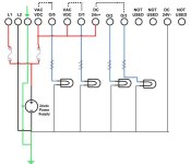
Perhaps a picture: See attached.

If you have it wired like this and are getting no voltage from the outputs then you may have a PLC with bad outputs.

Notice that you need to have 24vdc+ on each of the VAC/VDC terminals.

Not the ones that power the PLC but the ones that will pass 24vdc+ to your output when the contact is made in the PLC.
(See the dotted lines at the top to reference how these are grouped together)

(you already said you have the resistors in the circuit so I did not bother to draw them)


BCS
 
Output Terminal # Label Wire 1 Wire 2
1 DC IN +24V From source To input side
2 DC IN -24V From source To Input side
3 (Ground Symbol) Not in use -
4 VAC VDC Jumpered 24V -
5 Output 0/0 To output strip -
6 VAC VDC Jumpered 24V Jumpered 24V
7 Output 0/1 To output strip -
8 DC 24+ Jumpered 24V Jumpered 24V
9 Output 0/2 To output strip -
10 Output 0/3 To output strip -
11 Not used Jumpered 24V Jumpered 24V
12 Not used - -
13 DC 24V- - -
14 Not Used - -

• All outputs to strip go to their own resistor then to a 2-3V LED and have no continuity between each other
• PLC Type is 1761-L10-BXB
• I touch separate 24V to the terminals 0/2 and 0/3 and they lit up
• I did as Mr. Buford indicated, made and downloaded a program that had only the (END) rung and changed outputs 0-3 to a 1 and only the 0/0 and the 0/1 energized, 0/2 and 0/3 did not. ALL PLC indication lamps energized
• This PLC is suppose to be brand new
• Where does 0/2 and 0/3 get their power on this PLC?
• Is the DC 24V- connected to a ground? Terminal 13.
Sorry I had to do it this way but the website call my file invalid
 
Output Terminal # Label Wire 1 Wire 2
1 DC IN +24V From source To input side
2 DC IN -24V From source To Input side
3 (Ground Symbol) Not in use -
4 VAC VDC Jumpered 24V -
5 Output 0/0 To output strip -
6 VAC VDC Jumpered 24V Jumpered 24V
7 Output 0/1 To output strip -
8 DC 24+ Jumpered 24V Jumpered 24V
9 Output 0/2 To output strip -
10 Output 0/3 To output strip -
11 Not used Jumpered 24V Jumpered 24V
12 Not used - -
13 DC 24V- - -
14 Not Used - -

Not really sure what to make of all this.
You are showing that you are putting 24vdc+ and also 24vdc- on the outputs.

If you look at the drawing I gave you earlier you will see that the 24vdc- will just go straight to one side of your LEDs.

Then put 24vdc+ on all of the VAC/VDC terminals that are next to your output terminals. (example: next to O/0, O/1, etc)

Then come from your 1 of your output terminals (O/0,O/1,O/2,O/3, etc) to each of your LEDs.

Be sure to keep your resistor in the circuit to keep from smoking your LEDs.

If you wire it like this it will work.
Just use the drawing I gave you.

Here is a link to the ML1000 User Manual, although I do not see the Model # you say you have in the Manual.

http://literature.rockwellautomation.com/idc/groups/literature/documents/um/1761-um001_-en-p.pdf

Good Luck, and Good Night
BCS

EDIT:
I revised my drawing to show the power and ground terminals for the PLC to avoid any confusion.

My terminal layout may not be the exact same as what you have as I was unable to find your exact model # I did see the 1761-L10BWA and BWB and they both have a few less outputs than I show, but the principal is the same.

You put 24vdc+ on the VAC/VDC terminal and the Output that is grouped with that terminal will output 24vdc+ when true because a relay contact inside the plc will make and tie the two of them together compleating the circuit to the LED.

Just think of the VAC/VDC terminal as one side of a N/O contact and the OUPUT Terminal next to it is the other side of the N/O contact.
When the logic in the controller is TRUE then the contact will close and compleate the Circuit.

ML1000 OUTPUT REVISED.jpg
 
Last edited:
EDIT:

My terminal layout may not be the exact same as what you have as I was unable to find your exact model # I did see the 1761-L10BWA and BWB and they both have a few less outputs than I show, but the principal is the same.

Close Charles...

His is a L10BXB, the BXB has 2 relay outputs and 2 transistor out, so you need to also add + and - to the two transistor outputs, terminal 13 needs 24-
 
Well Ok then,
Like I said in my last post, I did not see the BXB in the manual that I gave him the link to.
Found 2, 1000 manuals online but neither had the BXB.

You got a link you can post?

BCS
 
Ok, lesson learned, dont wait until post #21 to ask for Model# of PLC being used. LOL

Anyway perserverance paid off.
Here is a link to the BXB manual.

http://www.ces-pasco.com/information_links/manuals/IO%20Wiring%20Diagrams.pdf


And here is a new Drawing for you.
Dont forget to leave your resistors in the circuit for the LEDs. I dont have them drawn in since you said you already have them.

BCS

L10BXB OUTPUT.jpg
 
Last edited:
OK Last post I promise.

It bothered me not showing a fuse for the outputs, so here is a revision with output fuse and resistors.

Best of Luck with your project.

BCS

L10BXB OUTPUT R2.jpg
 
I meant the fact that someone in today's "that's-close-enough" world actually CARED enough to go back and "fix" something that they could have simply just let "slide" ...

there aren't enough people around today who CARE anymore ...

I'm 68 years old - and I can easily see the difference in the attitudes that people (in all walks of life) have toward the quality of the work that they do ... things have changed over my lifetime – and not for the better ...

I am always amazed - and appreciative - when I come across someone who actually DOES seem to care – and who is willing to put forth an extra amount of effort to get a job done "right" ...
 

Similar Topics

I went on a service call yesterday for a Micrologix 1500. An output wasn't activating and they wanted to know what was hanging it up. It was a...
Replies
10
Views
2,808
I program with very basic operations, more like a shift register type seqeuntial format by just latching rungs etc. as program progresses. I never...
Replies
2
Views
3,521
Hi, I've come across a customer using IDEC Micro-1. FC1A-E1A1 & FC1A-C1A1 (Expansion unit). If not mistaken this Micro-1 is an obsolete model...
Replies
9
Views
7,401
hi all i am new here i have a mitsubishi smart touch hmi i.e ms-60t-pe but i cannot find a software to edit and download a program in it any help...
Replies
3
Views
163
FactoryTalk View ME running on PanelView Plus 7, connected to Compact GuardLogix 5380 PLC Customer is asking for a physical push button to be...
Replies
6
Views
182
Back
Top Bottom