using 1746-NI16I

Your latest program still does not have the Configuration set as your described. I will fix it for you.

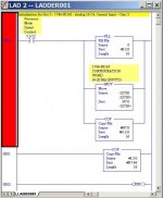
Here is all the logic you need to move I:3 data to N7:46.

JK-Test_Nitro Rev 1.jpg
 
Last edited:
and here is page 3... I was refreshing pg2 sorry

the data wasn't originally intended on going to 46 (I thought it was supposed to be at 0 originally but saw in the code that it was going to 30)

I also just reread the posts to see if I missed anything and just noticed you updated an earlier post. what does the value -16192 represent (maybe I shouldn't ask)

I told you I don't care about the fancy pants stuff, I just copied all that. I don't need the error checking. I am good if I just have a value to get to my HMI from the flow meter. That's all I care about.
 
what does the value -16192 represent (maybe I shouldn't ask)
No, ask anyway. It is the "configuration word" if your want your module to read voltage inputs. For current as you wanted, used -32720. That would confiure the module for Class 3 4-20 mA inputs, and Engineering Units.
 
The data wasn't originally intended on going to 46 (I thought it was supposed to be at 0 originally but saw in the code that it was going to 30)
Send it anywhere you want, but you cannot use the same address for TWO different things at the same time. Because you initially used the program in the manual, it used N7:0 to store the Input Module Configuration Word (although they did not label it as such - poor programming!). Because you used N7:0 to store that word, it is NOT SMART to then use N7:0 to store your analog data.

Two choices:
Use N7:0 to store your configuration word, or not.

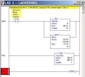
You do not really HAVE to store the configuration word (which Allen Bradley made sure NOT to mention in the example). You can just MOVE the value directly to the analog output addresses (but it would require 16 MOV's if you use all 16 Inputs). That would leave N7:0 free for your data storage.

You can do it like this to free up N7:0 for data storage. This only works for when you use the first input, I:3.0.

JK-Test_Nitro Rev 2.jpg
 
Last edited:
ok I understand that. There must be something in the input card from I:3.16 that they put at N7:46 too is it.

there seems to be an issue with the SCP. I have input changing at I:3.0 but not at F8:0 and there are I's where I usually see e's from errors.

this is what I mean:
05292012_ss02.bmp
 
Your Rung 0003 is NOT being scanned. The I's indicate that it has not been properly run through the mandatory 3-part procedure for an ONLINE edit. You must follow these steps, or else do an OFFLINE edit:

EDIT, ASSEMBLE, and then TEST your rungs, before they will actually become part of the program and execute the instruction. Click on Rung 0003, then select "Edit", then "Test Edits".
 
Last edited:

Similar Topics

I am looking to replace a SLC5/05 processor with an AENTR adapter. Configured the rack in a compactlogix. The connection to all of the cards in...
Replies
5
Views
2,323
Hello, We have an older SLC500 controlled system that is using a BASIC module to communicate to a third party device. Looking into converting the...
Replies
4
Views
1,282
Hello Upgrading to a ControlLogix processor using existing 1746 I/O (If it ain't broke why fix it?) Main Rack 0 - 13 Slot Chassis Expansion...
Replies
4
Views
2,680
Hi guys, I'd like to to ask I can use the 1746-IB16 with a rotary encoder from Omron E6B2-CWZ62. It's just for a training kit, I do not...
Replies
3
Views
2,033
I am running into a problem with the 1746-HSTP1 Stepper Controller Module for my SLC5/03. I am trying to get the stepper motor to just jog. I dont...
Replies
1
Views
2,535
Back
Top Bottom