Learning by Doing

Casey,

When you go Offline, I'll know you went out for another 6 pack of MGDs. 🍺


Anyway, To thoes in the know..

I've just noticed something. It seems that the lower byte range of V7633 is used to setup both mode 20 (up/down counter) and mode 30 (pulse output) Hmmmmm. Seems like you cant have your cake and eat it too?? So does this mean that one cannot have a stepper and counter? OR does this mean that the HO-CTRO counter module will be necessary to have the best of both worlds?

Inquering minds need to know.....
 
Originally posted by elevmike It seems that the lower byte range of V7633 is used to setup both mode 20 (up/down counter) and mode 30 (pulse output). So does this mean that one cannot have a stepper and counter? OR does this mean that the HO-CTRIO counter module will be necessary to have the best of both worlds?

What worries me is the fact that I don't even know enough to ask that question, let alone how to answer it. On the other hand, the mechanical aspects of this project don't concern me all that much. I've always been able to make something work, from a mechanical standpoint. One way or another. I've just been doing it for so long. But I'm daunted by the prospect of converting those 29 steps into something that will actually control the various mechanical elements of that machine. It's like I've told someone I'm a chess player when all I've done is memorize the rules for moving the pieces around the board.

BTW, I would like to know the answer to your question, too. The catalog description for the DL06 makes the statement that "For motion control consider one of these options already built into the DL06 I/O:

  • 7kHz max inputs for two up-only counters or one quadrature encoder
  • One external interrupt input or pulse catch input
  • One 10 kHz max pulse output, step and direction, or clockwise and counter-clockwise pulse outputs selectable

The catalog description doesn't emphasize the word "one", like I did when I typed it here. But it does sound like they are saying, without being too obvious about it, that you can only have either/or, not both.
 
Last edited:
Keep in mind, a stepper is not really necessary for this project, and the cost of a big enough stepper to handle the required load may scare you away anyway. In order to achieve good repeatability your going to have to have the encoder. Steppers like the ones AD is selling at reasonable prices are not very powerfull. Besides, aughough this is a moving object, I wouldnt necessarly consider it a motion control project. Consider a garage door operator, stops on a preset dime all the time, but no stepper involved. We use AC motors and Drives every day, (some open loop) and can stop within 1/16 in of floor level, and No stepper involved.

Dont worry about programming. Arik, Myself and others have already indicated that they are familar with this type of operation and are willing to help out with it. The big thing is your going to need a model to run it on at some point in time, so go ahead and build the unit.

Regards, Mike.
 
Hi Mike,

Garage door opener, eh? :unsure: What you're saying makes a lot of sense. Let me make sure I understand what you mean: Are you talking about a simple, synchronous AC motor (geared down as required) that is turned off and on in response to the pulse count from an encoder? I like that idea!

My only concern would be coasting of the motor once it had received the signal to stop. But it would be minimal when geared down to the speed required to drive the wire, and would, in any event, be more-or-less predictable.

I'm very interested in knowing the exact type of motor you're talking about here. Does continuously cycling a single-phase AC motor on and off for an extended period raise any serious reliability issues?
 
pstephens said:
I'm very interested in knowing the exact type of motor you're talking about here. Does continuously cycling a single-phase AC motor on and off for an extended period raise any serious reliability issues?

Actually youd be using a THREE phase motor. The drive power supply could be 1 phase, the drive would convert it to 3 phase. You can program the drive for full torque at very low, or Zero speed to stop and hold the wire.

Another option would be to use a Shunt field wound DC motor. The motor control could be set up similar to a drive, with maybe two speeds and to stop and hold you would stregnthn the field.

On elevators we use both setups discribed above. There are many options, and not any one is particularly right or wrong. It's more a matter of preference.

The wide variaty of Motors and Drives potentially applicable to this project kinda reserves me from making a reccomendation until I know more about the Load, actual speed, and power supply available etc... That why I keep saying build the feed mechinizem, then decide on the motor/drive. Once you have the feeder built you can then stick the wire in it and pull on the wire with a dyno guage at the desired speed, then you will know more about your motor requirements.
 
Last edited:
pstephens said:
My only concern would be coasting of the motor once it had received the signal to stop.

No thats not the way it works. In simple terms the motor/drive will be set up to dynamicly brake and hold the wire in place for cutting. Power will not necessarly be released from the motor. You can program many drives to hold the project in place but not for a long time.

pstephens said:
Does continuously cycling a single-phase AC motor on and off for an extended period raise any serious reliability issues?

Proper sizing is important to prevent overheating during the cycles. If the motor/drive is sized properly and you add a few % then this shouldnt be a problem. Think of it as an elevator. Start, Stop, Start, stop, etc etc.. all day long with cycles withing 10 or 20 seconds of each other.....and with a VERY high degree of accuracy. Again, Sizing is important.

When I pick a motor before building the project, I can do that only because I know what all the paramaters are before hand, due to expierance, and some ability to do a simple HP equation. But I already know the load, and the desired speed, duty, etc... Since you have no idea as to exactly what your HP/torque requirements are you dont have the luxuary of doing this. So the cart has to get behind the horse.

Of course you can guess, but there's some risk to that. Too much wont be too bad but may require more power than your supply can supply; And you may not stall in the case of an entangelment of some type, which could lead to serious damage to the equipment, or injury. Too little and your going to have the serious problems your worried about (not holding, overheating etc..).
 
Originally posted by elevmike Actually youd be using a THREE phase motor. The drive power supply could be 1 phase, the drive would convert it to 3 phase.

One thing I didn't mention about this machine is that the guy would like it to be mounted on wheels, so he can move it about the plant without too much difficulty. Therefore, a single-phase supply is desirable, though it's not a deal-breaker.

The wide variety of Motors and Drives potentially applicable to this project kinda reserves me from making a recommendation until I know more about the Load, actual speed, and power supply available etc...That's why I keep saying build the feed mechanism, then decide on the motor/drive. Once you have the feeder built you can then stick the wire in it and pull on the wire with a dyno guage at the desired speed, then you will know more about your motor requirements.

I appreciate what you're saying, but for a variety of reasons, mainly concerning my need to sub-contract the building of this machine to a local fabricator, that approach may not be a viable one. The calculations for determining the torque requirement are straightforward -- next week I will get the exact size and shape of the roll (I already know the weight), and the speed is a given. I'm confident that knowing this, and adding a generous safety factor to the calculation, would allow a drive to be sized with a reasonably high degree of accuracy.

Can you give me some particular brand names/types that you are familiar with, that you think might be suitable, just so I could start researching and learning more about the possibilities? All I've been studying for the past month or so has been steppers, and I'm kind of ignorant about some of the alternatives you're suggesting.

I really appreciate your help, Mike.
 
pstephens said:
One thing I didn't mention about this machine is that the guy would like it to be mounted on wheels, so he can move it about the plant without too much difficulty. Therefore, a single-phase supply is desirable, though it's not a deal-breaker.

No problemo... In that case...the power cord is going to be SINGLE phase if that's what you want. The drive is going to rectify the power, and convert it to THREE phase for the motor.

I have to think about and search around for the answer on the motor drive issue. I'm gonna guess that 1/2 HP might just do. I'm not so use to doing little motors so I need some time on this and have a family event to attend this afternoon. So later on that.. In the mean time take a look at the motors and drives on AutomationDirects web site. Peruse the manuals for the drives and youll start getting the idea...

Gotta go for now.. Have a great Sat The weather in Detroit is Great!!
 
Last edited:
elevmike said:
Peruse the manuals for the drives and youll start getting the idea... Gotta go for now.. Have a great Sat The weather in Detroit is Great!!

Sounds like a plan! Weather's nice here, too -- a little windy. Talk to you later!
 
For this kind of application the solution is not AC motor.(according to my opinion)
But from other hand is the cheapest solution.
You might pay for that in the feeding speed.(12'/sec.)
When you come to chose VFD I would consider to use Omron Or Yaskawa
J7.
In that case I can provide you complete system and support for that.
I have several systems like that.
The J7 have good dynamic quality and very easy programming.
I can to recite to function during I snoring at night.
0.37KW cost here about $150 0.75KW about $180.
For your portable machine I would chose 240V VFD not 110V.

Just to clear my self.Stepper motor design for this kind of application.
Speed and accuracy simplicity and cost is the main advantage.
The disadvantage is they are not made above certain size.(then we go for servo motors)
So if you can fit your systeme to step motor you will get better system.Reduce the motor speed and get higher torque.
If you can not do that then go for AC motor.
From quick look at AD web site, the bigest stepper system cost $360.
Its cheaper the AC system.(motor geae and VFD)
I aware to the fact that stepper is more complicated to implement then AC motor.
Sometime the hard way is the short way(it so true in this profession)
All the rest is in your hands.
 
Arik, and pstevens..

Nothing like the designing by commitie...Kinda like making sausages and laws... ;)

Regarding the motor issue... :unsure:

I'm gonna give a SWAG (Simple Wild A$$ Guess) that it will take about 50 ft lbs of force to drive the wire through the driving rollers, and pull the 500 lb reel, IF the reel is on a good set of bearings. That's like 800 oz of torque? right? So if my swag is anything near what the actual demand is AD steppers may not due the trick , unless there is some gearing down with the pully system. Like at least 2 : 1. Since speed isnt an issue then you can use the max torque capabilities of the motor, and keep down the inertia of the reel.

But...I'm gonna say that I'm not convinced that a stepper will have the necessary power for this system. That's my only concern with it. Im sure that part of my problem is my lack of expierence in real world stepper applications. So Arik, maybe you can point us to a setpper motor system that you are SURE will have the power and speed necessary for this system??
 
Hi Guys,

Mike, I believe you're way high on your SWAG. I've done a lot of studying and calculating on this setup, and it really comes down to the moment of inertia of the moving mass (the 500# roll of wire, plus the turntable device that carries it) and the desired acceleration rate. Of course, there are also nominal friction losses in the system that may just have to be estimated.

The amount of torque to rotate the mass at the desired speed (about 10 RPM, in this case) yields the running torque, which needs to be added to the acceleration torque (the torque required to accelerate the mass to the desired speed, in the desired time interval) to give the total torque requirement. This would be a maximum amount, as the acceleration torque only applies at startup.

The equations used to arrive at these torque values are based on rotating the load directly, thru its own axis of rotation. If the OD of the roll of wire is 24", and the OD of the driving roller is 2", there is a 12:1 mechanical advantage. And if the driving roller is driven by the motor thru a 3:1 gearbelt reduction, then there is a total mechanical advantage between the output shaft of the motor and the driven load of 36:1. This reduces the effective torque requirement considerably.

Since I'm still waiting on the exact dimensions of the wire roll, I can't calculate the total torque requirement at the motor, but I'm guessing that it will be something less than 12 in-lbs. (This is figuring on the wire roll rotating at about 10 RPM, and allowing a generous 2 seconds to accelerate to the desired speed of 12"/sec.)

The 12"/sec wire speed translates to around 360 RPM motor speed.

HP = (RPM x TORQUE)/63,000

HP = (360 x 12 in-lb)/63,000

HP = .07 approx.

This is not figuring in frictional loads and losses, nor a design safety factor.

Of course, stepper motors are not normally rated in horsepower, as AC motors generally are. But for comparison, the largest stepper motor that AD sells has a max. torque output that goes from around 20 in-lb. at 40 RPM to around 3 in-lb. at 500 RPM (in half-stepping mode). Which kind of tells me that it's on the borderline as far as working in this application. Pretty much like you figured.

This is all FWIW, as I'm still flailing for absolutes at this point.
 
Last edited:
I dont have all the data to calculate the pulling motor size.
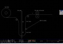
But from systems I made the control. the designers make buffer by driveing the feed roll between 2 sensors so when you pull you need power only for the buffer not for 500 leb.
in that case you pull few leb.
the big advantage is you avoid sliping in the pulling rolls if the wire in tension.It work with all kind of web and wire too.It mean more accurate system.
pstephens can know what the power he need to pull when he got free loop.


I made this draw to show the way I see it.Its too late half past mid night so I wile be back
tomorrow.We have 7 ot 8 hours gap.

P.S.I am sorry for the way my drawing look like.

wire pull.jpg
 
Last edited:

Similar Topics

Hello everyone. I am currently doing a project to teach about ethernet topologies such as ring or bus. For example. But instead of using an...
Replies
8
Views
4,344
Although I did not title it as such the last chapter would have been the PID. Learned a lot will give the details in that post. SO on to the...
Replies
20
Views
10,565
I've gotten to the learning curve where I can program a call for pump to come on at set point but I'm not sure how to turn the same pump off when...
Replies
1
Views
130
I want to pick up an Allen Bradley PLC so I can practice writing programs. I have 10 years as a maintenance tech and a good understanding of...
Replies
8
Views
233
Hi all, i have started a new chapter in my career with a local company. a lot of their plc's is omron and i have the cx version 9.75 software...
Replies
25
Views
4,225
Back
Top Bottom