1769-IF4XOF2 - Setting up analog in

desertsurf520

Lifetime Supporting Member
Join Date
Jan 2018
Location
Tucson, Az
Posts
61
I am getting max counts on my analog input 32640 on a temperatur transmitter. I have a compactlogix L24ER and I added a 1769-IF4XOF2 in slot 2 (only additional module). I have used an SCL to scale the analog data but it only reads max value. I didn't realize there seems to be a few more steps with this combo analog/in/out card. I looked up the manual and set the control bits enable-in to 1 (0-3) downloaded and rebooted PLC but still don't have a valid reading. I have a local display that shows the PV output. I must be missing something.
 
I don't recall any special setup required with them, but it's been a long time since I've used them so take that with a grain of salt. Are you sure it's wired correctly?
 
Well, I didn't really think there was much of a special setup because I've done it before but maybe not with this module and different version of Studio. I did look it up here and it seems there are control bits to set up in tag viewer. It seems pretty easy but I am getting max range. I looked up the manual and it indicates its not as straight forward as setting up 0-20 or 4-20 in the card settings. Either, way it is not working.

I have the analog in goint to I in 0+ V/I in 0- jumped out ANLG Com and that goes back to zero volts at the power supply
 
I pulled up a V20 program with one of those. If you look at properties of the module in the I/O tree, there's an input configuration tab. Make sure the inputs you want are enabled. Looking at module configuration tags (Rack:Slot:C) i see the inputs enabled with 1 which is probably redundant with the check boxes in configuration.

For 4-20 mA, the input scaling for these in this program is 6272 minimum, 31104 maximum. I didn't write it, so I don't know why those numbers. The manual says 0 to 21mA is 0 to 32640 which looks to me like 6217 to 31086 for 4-20mA.

It sounds to me like you have a wiring problem. Your description sounds right for the module side. Check out the transmitter side and make sure you are connected to a current output, and scaling is properly set in the transmitter.
 
Its a 2-wire transmitter and the local display is reading correctly at ambient temperature.

I wired it according to the manual. Maybe input zero is bad. Ill try another one.
 
2-wire transmitter with a local display. can you show your wiring diagram?
2-wire transmitter would be loop powered so you are getting 24 VDC from somewhere maybe the local display. local display mA input and plc mA input would be in series unless you have a mA splitter or repeater.
 
Negative from the transmitter goes to the I in 0+ from there V/I in 0- jumps to the analog com terminal and there it jumps to the negative of the power supply. I know I have the correct current and the loop is connected because the display is correct and its HART transmitter, and I can see the current signal and PV. But I watched some videos where they adjust the analog input from 0-10V to 4-20 mA but I don't have the selection in the module settings.... maybe thats the issue?
 
I've had a similar thing happen on a MicroLogix where the input was reading full scale because the input was set to 0-10V instead of 4-20mA, but I can't think of why it wouldn't show the selection on your module. I know some MicroLogix modules have DIP switches you have to set, but I've never experienced that on a CompactLogix I/O card.
 
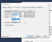
So just as a test, I did create a test project with an L24ER and went to add the same module, it does let me select the input range if the channel is enabled, screenshot attached. What does it show under your Input Configuration tab? For the disabled channels (2 and 3 in my screenshot), the dropdown is greyed out and I can't click it.

EDIT: I'm just spitballing here because I don't have any sort of PLC I can bench test it with, but are you trying to change the configuration while online with the processor? It might only let you do it offline and download to the controller.

1769Analog.PNG
 
Last edited:
Ok. No, I am mistaken. I put in the 1769-IF4XF0F2 but that is the wrong module. When I put in the correct module 1769-IF4XOF2 it does NOT have the signal type as a selection. 0-10 vs 4-20.

Am I supposed to add it under expansion or under 1769 bus?
 
Ok. No, I am mistaken. I put in the 1769-IF4XF0F2 but that is the wrong module. When I put in the correct module 1769-IF4XOF2 it does NOT have the signal type as a selection. 0-10 vs 4-20.

Am I supposed to add it under expansion or under 1769 bus?

I just checked and I also added the wrong module. When I add the IF4XOF2 it only lets you enable/disable analog inputs on the Input Configuration tab.
 

Similar Topics

I have Studio 5000 v30 and trying to set up an analog input. I noticed through another thread there are extra steps. I looked up the manual and I...
Replies
1
Views
519
Hi all wiring in the above card and the PDF from AB is fairly vague in showing how to wire in a current output. I am connecting a sampson valve...
Replies
2
Views
2,565
This is my first time using a 1500. Now that it's installed I see that the minimum change (input) is 128 bits. I suppose this is what's meant by...
Replies
7
Views
2,097
If you notice on the bottom right it looks like two little clips coming off the module. A third clip should be just to the right of the two you...
Replies
0
Views
1,534
Does anyone know what the data transfer rate for this series of CompactLogix PLC's? 1769-L24ER-QB1B to be exact. Cheers.
Replies
1
Views
98
Back
Top Bottom