1769-IF4XOF2 - Setting up analog in

Yes, it is absolutely Slot 2. I have a meter that can source voltage and it is reading exactly what it should be. Not mAs on the mA input....

Have you tried the other current/mA inputs? Is input 0 still reading full scale even when you source from your meter?
 
The user manual says that the mA input has an input impedance of 150Ω.
What voltage do you measure between "V/I in 0-" and "I in 0+" when the sensor is connected? Do you have a way to measure mA?
 
Have you verified your V/I in0- AND your ANLG Com on your module are connected to your 24VDC-?

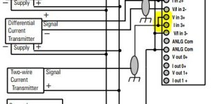
Have you jumpered your V In 0+ and I In 0+ together? The manual for the low res. model does not show them jumpered together. However, the manual for the fast module does.

I am feeling a sense of Deja Vu here and remember having an issue similar to yours. I believe the manual for the low res. module may be incorrect.

1769 Fast module.JPG 1769 Low Res Module.JPG
 
I found a tech note (access level: Everyone):
https://rockwellautomation.custhelp.com/app/answers/answer_view/a_id/561206/loc/en_US
It says to "jumper ANLG Com to V/I in e-" where "e" is the channel number when using single-ended inputs. Not sure if that applies to you or not. That's also shown in the manual.

Another one talks about the value freezing due to noise on the line:
https://rockwellautomation.custhelp.com/app/answers/answer_view/a_id/974722/loc/en_US

I also found a note on page 87 of the manual:
The four input channels for this module are not configurable. Each
input channel supports either 4 to 20mA current or 0 to 10V dc
voltage. This choice is determined by the module terminal to which
you are wired. There is a current and a voltage terminal for each
analog channel.
So that supports the fact that there is no configuration tab in the module properties.
 
Yes, the wiring diagram shows that the v/i neg needs to be paralled with the analog com and then to power supply negative. Thats all done correctly. Ive done that before.

I think its defective. The Voltage signal works fine. the mA does not.
 
Have you tried jumping the I in0+ and V in0+ together? If you think the module is bad anyway, what have you got to lose?

If you do replace it, I'd suggest replacing it with the 1769-IF4FXOF2F module since it has more capability and fewer issues. According to its wiring diagram the I in0+ and V in0+ will need to be jumpered together, anyway.

Let us know what you figure out.
 

Similar Topics

I have Studio 5000 v30 and trying to set up an analog input. I noticed through another thread there are extra steps. I looked up the manual and I...
Replies
1
Views
519
Hi all wiring in the above card and the PDF from AB is fairly vague in showing how to wire in a current output. I am connecting a sampson valve...
Replies
2
Views
2,566
This is my first time using a 1500. Now that it's installed I see that the minimum change (input) is 128 bits. I suppose this is what's meant by...
Replies
7
Views
2,097
If you notice on the bottom right it looks like two little clips coming off the module. A third clip should be just to the right of the two you...
Replies
0
Views
1,534
Does anyone know what the data transfer rate for this series of CompactLogix PLC's? 1769-L24ER-QB1B to be exact. Cheers.
Replies
1
Views
98
Back
Top Bottom