Assigning Priority Based on Run Time in CCW

mnwinter

Member
Join Date
May 2020
Location
Seattle
Posts
12
Hey everyone I'm working on a PLC project for a series of 4 vacuum pumps. I need to be able to rotate each pump into a different priority based on run time.


So we have a factory that runs vacuum packers. Sometimes we run 5 some times we run 1. I have already created the program and turns the pumps on and off based on the demand. The more draw the more pumps turn on the less draw the more pumps turn off after a set amount of time.

Now however pump 1 has 4 times the amount of run time as pump 4. So I am trying to find a way to get the pumps to rotate into a priority position based on the amount of run time.

I don't think I need comparators for all four pumps, I was thinking that if I just take all the timer readings from all 4 pumps and just set it to say when one pump is more them 250 hours less than the others it goes to priority one. There would be no need to check for priorities 2, 3, and 4. If you just rotate the lowest hours pump into priority then it should keep all 4 pumps more or less even within the range set...... But then how would you write that in CCW...

Any help would be greatly appreciated.
 
Depending on the life expectancy of the machine / life expectancy of the pumps, it may be better to drive 1 pump into oblivion. This way, you replace one pump per year, rather than have 4 pumps fail all at the same time in year 4.


So you just have maintenance press a button, to move priority to motor 2, when you replace motor 1 for a brand new one.


...4 vacuum pumps... Sometimes we run 5...
Your operations manager should be proud.
 
Depending on the life expectancy of the machine / life expectancy of the pumps, it may be better to drive 1 pump into oblivion. This way, you replace one pump per year, rather than have 4 pumps fail all at the same time in year 4.

While I don't disagree with the sentiment, I always think it's wise to make sure the every device gets a run at least once a week. Otherwise on year four, pump 1 fails catastrophically, and it's only then that you learn that all the seals have perished in pumps 2-4.
 
Just throwing some numbers out - run them 40/30/20/10% of the time until motor “40” is replaced, then shift the remaining up, run the new one 10%.

How are you handling switchover now?
 
Last edited:
Ok, maybe not clear we change the number of pumps ran daily. All 4 pumps must be ready to run at all times. Including all 4 at once.

I just need a way to rotate them based on hours automatically.
 
By "daily" do you literally mean once a day?


Or is the number of pumps running determined continuously, via lead/lag or split range control or similar?
 
Vacuum pumps run in automatic mode where if the pressure drops below a certain point the next pump kicks on if in x amount of time it's still not reached sufficient pressure another pump kicks on. If we are holding max pressure it kicks the last pump off if after x amount of time were still holding max pressure the next pump shuts offs. So if production calls for 3lines to run the system will adjust based on the amount of vacuum pumps needed to run 3 lines. Or say one line runs out of product and shuts down. The system will automatically adjust how many vacuum pump are needed to run.
 
what is the smallest time increment of pump runtime you want to accumulate? e.g. seconds, or 0.01h (36s), or 0.25h (15min=900s)?


that is, if a pump runs continuously for less than the increment, the code does not accumulate it?

Actually, doesn't CCW have rententive timers?
 
The thread and post here does something similar; that link takes you to the denouement but it would be worth reading the entire thread at least to that point.

It has three vacuum pumps running in a lead/lag1/lag2 configuration to control a vacuum, and a retentive timer to rotate the lead pump over time to balance the runtime long-term. It's not exactly what you asked for but it might achieve the same goal. It also deals with the case of a bypassed pump e.g. for maintenance.

I think I remember another discussion of how much, and even whether, that approach actually balances accumulated runtime across a set of devices, but given the comments in this thread, e.g. running pump 1 to oblivion so all pumps don't need maintenance at the same time, maybe that's a good thing.
 
Comments welcome but FYI this is my First PLC program I am sure I could have done a lot of things better but so far it works was we need I just need to be able to spread out the run time on all pumps that's what my boss wants.
 
... this is my First PLC program ...

Thank you for providing your code.

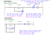
We've all been there, so I'd like to take a step back. The first two rungs we see are the Start and Stop rungs below*. There are two canonical ways to start and stop a process or sub-process: the Start/Stop Pattern (see this link); and the Set/Reset Pattern (see this link). One reason for using the Start/Stop pattern is that the process should always be put in its stopped state when the PLC mode changes to Run (e.g. after a power failure and recovery). One reason for using the Set/Reset pattern is that the process should be returned to its previous state, started or stopped, when then PLC mode changes to Run.

Looking at your code, it seems that you have confused the two patterns:

xxx.png

I am not saying the code does not work as is, but it does mean that your code is more cluttered than it needs to be, certainly on these two rungs and therefore likely elsewhere, which will make adding new features, such as runtime balancing, more difficult.

Also, while there are some comments in the code, it is very brief; it would be helpful for others here, and more so for yourself a few months from now doing diagnostics, if there was more a detail comment on the reason and behavior of each rung. Comments should describe what is happening in the process (e.g. "Switching to manual or pressing Stop button stops the process"); comments do not need to describe the logic instructions (e.g. "XIC of Manual bit or XIC of Stop bit will cause Reset instruction to reset System_1 bit"), because it is assumed the reader can read the logic.

Again, we have all been there I am not trying to embarrass you. But with experience will come a recognition of things like these. Also, it will be difficult to communicate in this forum unless there is more of a common understanding how PLCs work. I strongly suggest you commit to memory at least the Start/Stop pattern and the Set/Reset pattern, and look at the other patterns on that website (see this link). Further, you will benefit from watching Ron Beaufort's excellent bootcamp primer series, comprising less than a dozen videos and taking less than a couple of hours; see this link.

* I removed the XIO Toggle_1/_2/_3 instructions for clarity.
 
Last edited:
Okay, I have decoded your program, more or less.

The answer to your original query is in my .signature below: "There is no software problem that cannot be solved with another layer of indirection."

Basically you will insert a new "layer of indirection" between the No_Draw_Timer_1/_2/_3 bits and the _DO Pump_1/_2/_3 discrete output bits.

As it stands now, when in automatic mode (System_Run is 1), the code runs like this:
Code:
                                      [B]No_Draw_Timer_N[/B]     [B]Pump_N[/B]
--+--<misc logic evaluating to True>--------]/[--------+----( )-------
  |                                                    |
  +--<other misc logic evaluating to False>------------+
That is admittedly oversimplified, but that is how it functions when the two <misc logic> stanzas do not change from True and False.

So "No_Draw_Timer_N" is the semantic equivalent of "Do_Not_Run_Pump_N"

You are going to change that to
Code:
                                      [B]No_Draw_Timer_N[/B]    [B][COLOR=magenta]Lead/Lag_N[/COLOR][/B]
--+--<misc logic evaluating to True>--------]/[--------+----( )-------
  |                                                    |
  +--<other misc logic evaluating to False>------------+
Where Lead/Lag_N is one of Lead_1 or Lag_2 or Lag_3, which are non-temporary BOOLs, along with nine others to complete the new "Layer of Indirection" that you will create:
Pump_1_is_Lead_1
; Pump_1_is_Lag_2; Pump_1_is_Lag_3;
Pump_2_is_Lead_1
; Pump_2_is_Lag_2; Pump_2_is_Lag_3;
Pump_3_is_Lead_1; Pump_3_is_Lag_2; Pump_3_is_Lag_3.

The existing logic will control Lead_1 the way it now controls Pump_1, and the four BOOLs [Lead_N, Pump_1_is_Lead_1, Pump_2_is_Lead_1, and Pump_3_is_Lead_1], plus new logic, will control which pump is turned on when Lead_N is 1.

Similarly, the existing logic will control new BOOLs Lag_2 and Lag_3 the way it now controls Pump_2 and Pump_3, respectively, and four BOOLs, plus new logic, will control which of Pump_1, Pump_2, and Pump_3 turn on for each of Lag_2 and Lag_3.

The new logic will look like this:
Code:
      [COLOR=magenta][B]Lead_1[/B][/COLOR]     [COLOR=blue][B]Pump_1_is_Lead_1[/B][/COLOR]          Pump_1
---+----] [------------] [----------+-------( )----
   |   [COLOR=magenta][B]Lag_2[/B][/COLOR]      [COLOR=blue][B]Pump_1_is_Lag_2[/B][/COLOR]   |
   +----] [------------] [----------+
   |   [COLOR=magenta][B]Lag_3[/B][/COLOR]      [COLOR=blue][B]Pump_1_is_Lag_3[/B][/COLOR]   |
   +----] [------------] [----------+

      [COLOR=magenta][B]Lead_1[/B][/COLOR]     [COLOR=blue][B]Pump_2_is_Lead_1[/B][/COLOR]          Pump_2
---+----] [------------] [----------+--------( )----
   |   [COLOR=magenta][B]Lag_2[/B][/COLOR]      [COLOR=blue][B]Pump_2_is_Lag_2[/B][/COLOR]   |
   +----] [------------] [----------+
   |   [COLOR=magenta][B]Lag_3[/B][/COLOR]      [COLOR=blue][B]Pump_2_is_Lag_3[/B][/COLOR]   |
   +----] [------------] [----------+

      [COLOR=magenta][B]Lead_1[/B][/COLOR]     [COLOR=blue][B]Pump_3_is_Lead_1[/B][/COLOR]          Pump_3
---+----] [------------] [----------+--------( )----
   |   [COLOR=magenta][B]Lag_2[/B][/COLOR]      [COLOR=blue][B]Pump_3_is_Lag_2[/B][/COLOR]   |
   +----] [------------] [----------+
   |   [COLOR=Magenta][B]Lag_3[/B][/COLOR]      [COLOR=blue][B]Pump_3_is_Lag_3[/B][/COLOR]   |
   +----] [------------] [----------+
N.B. Analogous to Sudoku, exactly one of the three Pump_N_is_Lead_1 BOOLs will be 1 at any given scan; similarly, exactly one of the Pump_1_is_L..._N BOOLs will be 1 for any given scan.

The nine new Pump_N_is_L..._M BOOLs will be controlled by the code that keeps track of pump runtimes: generally, when the switch is mad, if pump X has the most runtime, then

  • the single BOOL Pump_X_is_Lag_2 will be 1, and
  • the two BOOLs Pump_Y_is_Lag_2, where Y is not equal to X, will be 0, and
  • the two BOOLs Pump_X_is_Lead_1 and Pump_X_is_Lag_1 will also be 0.
 
Last edited:

Similar Topics

I can't seem to figure out how to add descriptors to I/O points on an RMC using PCCU. Say, for example, I want to use "Valve_1" as a descriptor...
Replies
0
Views
75
Hello all. A little ashamed of myself that I can't remember how to do this but..... I have a 1734-AENT that I set the wheels to "888" applied...
Replies
9
Views
4,084
Hi all, I am in the throes of commissioning a single S7-1517 cpu and I'm utilising both ethernet ports, X1 and X2, with individual IP addresses...
Replies
2
Views
1,721
With FactoryTalk ME is it possible to use a single Trend object and list of pens being displayed using macros? Would like to have one Trend object...
Replies
2
Views
1,770
I had a 1794 AENT ethernet adapter card go bad. Tried to replace and cannot seem to get the replacement to work. I've tried everything I could...
Replies
0
Views
1,871
Back
Top Bottom