Can you recommend the proper direction on SLC500

It will be easier if the display writes the individual bits to 'B' registers. One to B3:0/0, next to B3:0/1 etc. Writing to Inputs will get overwritten by any physical inputs which you may have in your system with the same address. It is best just to stick to the 'B' registers.
 
How close am I on the logic?
You are close, but my old Daddy always said that "close" only counts in the game of horseshoes and for hand grenades.

With 16 PLC outputs, theroetically you can select up to 64 different keyboard keys, using two data lines X and Y. So it seems to me that you only need one 16-output relay module, one OW16 for your SLC-5/03.
 
Last edited:
NO - No - double coil!!!

One rung for each output connected to the 'X' terminals
One rung for each output connected to the 'Y' terminals

A total o0f 16 rungs

Each rung will have, in parallel, all of the bits from the HMI which turn on that particular output. Each bit will obviously appear in two rungs, one for an output to the 'X' terminals and one in an output to the 'Y' terminals. Each output should occur ONLY ONCE!!!!
 
Bernie,

If you look at the Proface manual, you see that each "switch" on the touch screen gets written to a specific memory address (NOT TO X AND Y BITS). So the PLC program must decode those bits back to X and Y data lines for the keyboard simulation.
 
Last edited:
Look at your PDF

If B3:0/0 is ON and B3:0/1 is OFF what is the state of O:2/0?

Unstated in my previous post but assumed is that (if a full 64 buttons on the screen are used) then each rung will have 8 bits in parallel.
 
Since I can program my Proface, I have been working on the button designs and what types of button assignments.

I came up with needing:

Momentary output or Bit Set? Not sure on this. Easy to change once I know this answer.

Right now all the same operation address are the same B3:0/0 . At some point I figure I need to assign each button a different address based on what is in the PLC.

I have already mapped the 'old' X Y matrix for the exact keystroke function. So, I know in the PLC is X0 Y0 is 'on' then I will get Coolant on at the machine. This keystroke however on the 'real' world use is a toggle button. Push it once for on, push it again for off. Thankfully there are only 4-5 keys that toggle this way. Most are one push to do something, and it is that one something only.

Thank you for your help in the ladder logic. I have been reading and reading on trying to decide what the logic would look like for the PLC. The HMI is alot easier to understand and do.
 
Here is how I understand it today.

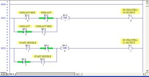
I found some one shot info and decided the coolant and 4 other buttons will need to run like this. turn on and off with the same button. that is the way the other keyboard worked.

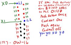
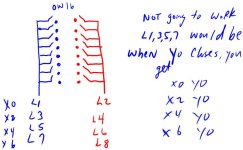
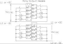
I have attached the relay drawing as I understand the way the input will be at L1 and L2 on each of the 4 1746-OW16 's.

X0-X7 is not controlled in any way by the ladder logic. It is hard wired to the L1 L2's of each module.

Y0-Y7 are controlled by the relays closing based on the respective button pushed on the HMI ( Proface 577R ) with a B:?/? address per button.

Attached ladder logic for the flip flop buttons only. Can a OSR be used on the seal control type setup? Does it need to be?

KEYGEN.JPG RELAY.JPG
 
In your first attachment, the OSR will only fire once per false to true transition of the preceding logic, therefore O:1/0 and O:1/1 can only be on for one PLC scan.

Are you sure the old keyboard latches those signals and it's not a mode that is "sealed" by the 286?

I would suspect that all the old keyboard buttons are momentary, but I could be wrong...
 
Hmm - the way I described the wiring hookup it would need only one module. The way you propose may take 4 modules. Wel;l - whaatever works in your mind.
 
I think Bernie had it right, let's see if I can explain it differently.

Rung for X0 output will be 8 parallel XIC instructions and one OTE.

The 8 XIC will be ButtonX0Y0, ButtonX0Y1, ButtonX0Y2, ButtonX0Y3, ButtonX0Y4, ButtonX0Y5, ButtonX0Y6, ButtonX0Y7.

Rung for Y0 output will be 8 parallel XIC instructions and one OTE.

The 8 XIC will be ButtonX0Y0, ButtonX1Y0, ButtonX2Y0, ButtonX3Y0, ButtonX4Y0, ButtonX5Y0, ButtonX6Y0, ButtonX7Y0.

So when you press buttonX0Y0, outputs X0 and Y0 go on.

There should be no need to program toggle functions, unless those were implemented in the physical keyboard (doesn't look it).

So, to reiterate. The proface writes to 64 bits in the PLC. I am calling these buttonX0Y0 thru button X7Y7. Actual address to your taste.

16 rungs controlling 16 outputs should replace the old matrix. Your knowledge of the old matrix will allow you to assign the function of each button and label them properly on the Proface screen.
 
Guys, I am fine with not understanding the ladder logic right now, but you have me lost on the hardware, and I think I should know the hardware 100%.

I have looked at this OW16, followed the traces, looked for schematic layouts on rockwell's site.

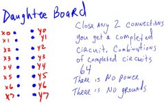
The best I have come up with is the L1 and L2 are common runs. That is 2 of something common. 2 would be X0 and X1 on one module. Y0-Y7 would be all the little screws to the relays that close and open.

I am not seeing how you can get 64 discreet outputs combination's from one OW16 module. Even if each relay was on its own path of connection, there would be 32 screws in that module for connection points. There is only 18 screws, and 2 of those are the common points for L1 and L2.

Unless you are talking about using a different module than the OW16.

relay_layout.JPG
 
Last edited:
OK, I'm looking at the picture with the original keyboard. If we are talking about replacing just the keyboard (that is my understanding) then you have 17 lines to connect at the plug. X0 thru X7, Y0 thru Y7, and a common. On the OW16, wire Out0 to X0, Out1 to X1, and so on. Out8 to y0, Out9 to Y1 and so on. The VDC-VAC0 and VDC-VAC1 terminals get wired together to your common. Unless I am really misunderstanding the application, that should do it.

The PLC program will take the 64 buttons on the screen and for each button pressed, make one X output and one Y output close for 64 combinations. We shouldn't have to deal with toggle functions or what happens when a second key is pressed. If all we are doing is replacing the pc board with the buttons on it, those functions will remain as they were.
 
Last edited:
OK, your terminology threw me off. You referred to X0-X7 and Y0-Y7 as inputs. They aren't. One set are outputs controlled by the interface. I'm going to assume for the sake of discussion that Y are the outputs. What the interface does is turn Y0 on, and then check for signal on X0-7 to see if any buttons are pressed. Then it turns Y0 off and turns Y1 on, and checks X0-7 again. It repeats this process for Y0 thru Y7 and then starts over. It does this pretty quickly.

Another basic misunderstanding is this idea that there is no voltage or current present. It just isn't so. It may be very low voltage and current, and it may be there for a very short time, but it must be there.

Now to the question of can you replace this with a PLC. Sure, but as you have been trying to make us understand, it's not as simple as I was describing.

OK, say we use 4 OW16 cards. Wire Y0 to the VDC-VAC1 of the first card, Y1 to VDC-VAC2 of the first card. Wire Y2 to the VDC-VAC1 of the second card, Y3 to VDC-VAC2 of the second card. Wire Y4 to the VDC-VAC1 of the third card, Y5 to VDC-VAC2 of the third card. Wire Y6 to the VDC-VAC1 of the fourth card, Y7 to VDC-VAC2 of the fourth card. Now wire all the OUT0 and OUT8 to X0, all the OUT1 and OUT9 to X1, all the OUT2 and OUT10 to X3, and so on.

The program for this setup is trivial. One rung per output. One XIC from each screen button, with one OTE for each output.

Reading back over the thread, this is pretty much identical to where you were on post 15.
 
Last edited:
The OW16 provides two commons. The first one is common for the first 8 outputs and the 2nd one is the common for the last eight outputs. So, with the OW16, you can have two separate circuits per card.

If you need isolation between individual relays, look at the 1746-OX8.


Paul

1746-OW16.jpg
 

Similar Topics

Good Morning , I have worked with many robot integrators through the years ,and was looking at Pearson Packaging Systems . Have many of you used...
Replies
4
Views
2,206
Hello PLCS.net! I'm about to program my first Robot soon! It's going to be a Fanuc. But wait, there's more! It's also going to be collaborative...
Replies
4
Views
3,364
I need to do some simple schematics, I don't need (and would never use) 3D modelling rendering etc. For those with long memories, AutoSketch would...
Replies
20
Views
8,496
Hello all, Is any good analyzing software. We have a bunch of data in text files. Need to analyse. Right now we are using DIadem. Is there any...
Replies
5
Views
2,283
Can someone recommend me a compact device to control logic on/off beacon according to signal from a PIR ? Some RTU maybe. I am newbie in...
Replies
6
Views
2,194
Back
Top Bottom