CompactLogix Analog Input Problems

Bering C Sparky

Lifetime Supporting Member
Join Date
Mar 2014
Location
Bering Sea, Alaska
Posts
1,117
Hello AGAIN,

Sorry for the plethora of questions today, but I must have brought some bad JUJU back to work with me, as I seem to be running into one problem after another with this.

Just sat back down and started working on this project again.
Hooked up the Analog Input using my process meter to simulate a 4-20 ma.

Connect it to Ch-0 to start with and could not see any value in the Monitor Tags Value colum. Also seen that there was a 1 in the Ch-0 Input Error Value Box.

Played around with it for a while with no luck, so I switched over to Ch-1.

Got a Decimal Value on Ch-1 once I connected the process meter to it, so just figured Ch-0 was bad out of the box.

Unfortunatly Ch-1 value just kept going slowly up regardless of the value I set my proccess meter to.

Disconnected process meter entirly and the value of Analog Ch-1 still kept climbing until it reached 32767 then it stoped and held that value, and now I have a 1 in the Ch-1 Input Error Value box, even when I re-establish the connection to the process meter.

Have used Analog for years with other Plc and Devices and never encountered anything like this before.

Anyone have any idea what may be going on here?
Leary to try it on another input until I can find a resolution to what the problem is.

EDIT: My Controller is a CompactLogix L24ER -OBFC1B and the AI is embeded.

BCS
 
Last edited:
never worked with your model - but my GUESS (pocket change only) is that the channels are configured/set up as VOLTAGE inputs - not current ...

on the models that I'm familiar with, you use different screws/terminals for voltage and for current - or there might be a series of jumpers or DIP switches to make the conversion ...

again (based on previous experience with OTHER models) you have to set up the analog channels in TWO places ... in the HARDWARE, you have to provide the correct electronic circuitry (with jumpers - DIP switches, etc.) ... you also have to tell the SOFTWARE how you're going to use each channel ... there's usually a screen/window for that ...
 
Last edited:
As Ron said, make sure the channel is configured in software as a current input. Also, note that with current inputs the positive line of the 4-20 is connected to BOTH the voltage AND current input terminals.

Keith
 
Hello Ron,
Thank you very much for your reply,

This is my first experience with this model also, and my first time trying to build a project in Logix5000 from the ground up.

There are seperate terminals for V+ and I+ for each channnel and V/I- share the same terminal for each corresponding channel.

I right mouse click on "Embedded Analog I/O under I/O Configuration > Embedded I/O in the Control Organizer Tree and select Poperties and then go to the Input Configuration Tab and change the Input Range -10 to 10 which is default to 4-20mA.

Have searched and searched and dont find alot of info on this controller.
I have the installation, programing guide and user manuals that I downloaded.
Have done searches on multiple forums.

It is a stange one.

BCS
 
As Ron said, make sure the channel is configured in software as a current input. Also, note that with current inputs the positive line of the 4-20 is connected to BOTH the voltage AND current input terminals.

Keith

HI Keith,
Thanks for the reply,
Well that is one I have not heard of but if you have experience with this then I will give it a shot connecting the Positive to both the voltage and curent input terminals.
Will let you know what happens.

BCS
 
Thanks Keith,
You-Da-Man

I still have a 1 in the Ch-1 Input Error Value Box
But my Analog Value is rock soild and on the money now.

Learing all the time.

Thanks again.

BCS
 
HI Keith,
Thanks for the reply,
Well that is one I have not heard of but if you have experience with this then I will give it a shot connecting the Positive to both the voltage and curent input terminals.
Will let you know what happens.

BCS

Connect your inputs exactly as the manual dictates.

I suspect that connecting your signal to both I-In and V-In is wrong.....
 
Hi Daba,

I have not found anything in the manual for this contoller that shows wiring diagrams.

But I have found wiring diagrams for the L23 controller and other analog expansion modules and you are right they do not show connecting to both the V and I terminals.

BUT I did just connect the way Keith said and it did work?

I dont have the background to say what is right or wrong here.

I have never ran into a problem like this with an analog input before. Usually just plug it in and configure it in the coresponding output, wire it up and move on. (In LOGIX 500 that is)
5000 is a new beast for me.

Hopefully others with L24ER experience will chime in and shed more light on the subject.

BCS
 
UPDATE:

After posting last I looked back at the Logic Tags and now magically have a 0 in the Ch-1 Input Error Value Box.
I changed nothing to make this happen.

Huh, go figure.
I am starting to think this controller has a gremlin living in it or something.

BCS
 
Don't blame the hardware. Look at the user.
Especially since you don't have experience with the hardware, 99% of the time the problem is that "You are Doing it Wrong".


Don't assume anything based on your past experience.
Wire it EXACTLY as it is in the manuals.
Configure as in the manuals.

Instead of the process meter I would wire in a device and power the loop from the panel 24VDC power supply.
 
Connect your inputs exactly as the manual dictates.

I suspect that connecting your signal to both I-In and V-In is wrong.....

I've definitely seen 1769 analog input cards where the manual instructs you to connect the positive to both I in and V in to use the current input. Can't remember exactly which ones but I've definitely put it on my drawings and wired them that way before
 
Hi GT,
I can respect your opinion there, I dont have experience with this controler or with Logix5000.

But other than not connecting the V & I together, not sure what else was user error (or DOING IT WRONG) in this case. Not to say that I dont make mistakes, hell I make them all the time, especially when working on something I have never seen or touched before, anyone who would say they dont is probably not being very truthful.

If AB has a wiring diagram for this controller, well I have yet to locate it (not to say there isnt one, I just have not found it), so was driving blind in this case. (cant wire it like the manual shows if the manual dont show it)
I did wire it like similar AB contoller manualls say to, and it did not work.

Power is comming from the 24vdc power supply, I am just passing it through my proccess meter to simulate the 4-20ma.
Dont see how that is any different than connecting any other device to achive this. 4-20ma is 4-20ma no matter how you go about achieving it.

What would you use for a 4-20ma output device for bench testing analog, a pressure transmitter, level transmitter, or some other thing that would require an additional outside force to vary the signal, this would require much more than connecting 2 leads on your meter and turning on a switch?
Not sure why you would want to go through all that trouble but thats just me.
Process meter is my go to tool when troubleshooting Analog, its fast and convienent.

Thanks for your opinion & input though and have a great day.

BCS
 
Last edited:
The 1769-L24ER and 1769-L27ERM controllers have "universal" analog inputs which are different from anything else in the Compact or POINT I/O product lines.

That's why there are so many options when you configure them in RSLogix 5000, and why the wiring diagrams for other Compact I/O modules are not necessarily the same.

The User Manual for this controller is Publication 1769-UM021. I'm working from a 2012 edition so the page numbers may have changed.

There's a terminal layout for the embedded analog connector in Chapter 8 on page 174, with the options for when you use it for analog vs. resistance vs. thermocouples.

And there's a sketch on Page 175 and another on Page 176 showing how to connect differential or single-ended analog devices in voltage or current mode.

As Keith suggested and you confirmed, you connect the + terminal of your current loop simulator to both the V and I input terminals on this module.
 
+1 Keith

Bering C Sparky said:
...Have searched and searched and dont find alot of info on this controller.
I have the installation, programing guide and user manuals that I downloaded.
Have done searches on multiple forums...

...If AB has a wiring diagram for this controller, well I have yet to locate it (not to say there isnt one, I just have not found it)...BCS

I suppose it all depends on where and how you are searching?...

514204 - Analog Wiring Example for CompactLogix 5370 L2 Block Controllers
Access Level: Everyone

Also, in reference to the wiring diagrams used in the above Technote...

Ken Roach said:
...The User Manual for this controller is Publication 1769-UM021. I'm working from a 2012 edition so the page numbers may have changed...

Ken,

The latest User Manual is Dec 2012, which superseded May 2012...

1769-um021_-en-p.pdf

The page numbers you mention in the 170's don't seem correct for what I'm looking at. They refer to Chapter 7 - "Configure Distributed I/O Modules on an EtherNet/IP Network".

In Chapter 8 - "Use I/O Modules with CompactLogix 5370 L2 Controllers", the "Embedded analog I/O Points" section from page 183-188 is where the diagrams are. The same diagrams as used in the Technote are there, as well as others.

It must be the May 2012 version you have?

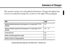
Attached is the summary of changes for the latest user manual. These changes must have shifted the page numbering by that much.

BCS,

Just to be clear...

For the CompactLogix 5370 L2 embedded analog inputs...

For Voltage analog inputs, you DO NOT connect Vin+ to Iin+ on the same analog channel.

For Current analog inputs, you DO connect Vin+ to Iin+ on the same analog channel.

Regards,
George

1769-UM21_SOC.png
 
Last edited:
Thanks Ken and Geospark,

I do need to learn to navigate the Rockwell information database, this is a true statement for sure.

I have just been using google to search for these items, and with our Sat-Link it can take a long time for PDF's to download, and often they freeze up and you can do nothing with them once they do download, (if they download at all) so it can be very time consuming and frustrating at times.

It is better than what we used to have though, which was nothing. (no internet)

Analog working fine now.

Thank you all for time and help, I do appreciate it.

BCS
 
Last edited:

Similar Topics

I had some recent issues with the analog inputs on an L23E. At first, I did not wire the analog com back to 24 neg and that was a lot of it...
Replies
34
Views
3,902
Hey guys, running into issues trying to get some analog input and output cards for customers needing a few points here and there. with that in...
Replies
15
Views
4,915
I am noticing odd behavior with a CompactLogix PLC I have here as a test unit. I have absolutely no I/O wiring on this unit, I just use it to...
Replies
2
Views
2,088
Hi All, Please see my below logic and AI configuration for a new Sick Laser DT500 that I am using for position feedback. The compute instruction...
Replies
3
Views
2,066
After reading the 1769-IF16C compact Logix analog input current module field wiring connection we noticed that it be used only with 2 wires and 3...
Replies
5
Views
7,942
Back
Top Bottom