How to wire a 24V Actuator with reverse polarities across motor to PLC

Your PDF says it is a 12V Dc Actuator - You could use 2 12V dc Supplies with a floating (0 Vdc)(-12 - 0 - +12)
then 1 relay per output 1 for fwd 1 for REV.
Not mush different to what has been suggested but easier to wire
 
yes use your output to fire the relay wire the relay to power the actuator fwd when on rev when off the limit switches will stop the travel
 
I'm really starting to sound dumb now :(

Using the output to switch the relay is fine. I dont understand how it can switch polarity when output turns off
 
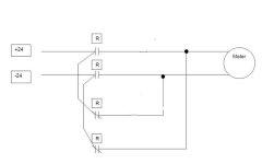
You would need a double pole double throw relay. Feed the +24V through one set of contacts N/O or N/C and the -24V through the other set. The N/C set of contacts would power the actuator when the output is off.

Now I don't know anything about your actuator, using this setup there would always be power to the actuator either + or -. I don't know if this would be an issue or not.

You mentioned a limit on the actuator. This could be wired in series with the relay in order to remove power to the actuator when the limit is reached.
 
Last edited:
Using one output is the easiest way if the device has a limt switch for each direction.

Parts you would need avaible PLC output and a single pole double throw relay.

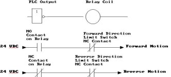
The trick is how you wire the relay. See attached drawing.

FR drawing.jpg
 
Something like this would work. You are only breaking one leg to stop the motor (similar to HVAC contactors). The limit switches should be NC - even though I showed NO.

actuator.jpg
 
Last edited:
Now I'm feeling stupid. From the spec sheet it looks like the limits are wired internally.

Bruce, aren't you putting 48V on the motor?
 
Now I'm feeling stupid. From the spec sheet it looks like the limits are wired internally.

Bruce, aren't you putting 48V on the motor?

They might be internally wired, but I'm not sure how they would actually do that since once one leg is broken by the limit switch, you could never put the reverse polarity on it to get it off the limit switch.

I never intended to put 48 VDC on the motor. Some places call the common side of 24 volts as -24VDC and some call it 0VDC and some just call it Common. I was just intending to show the potential difference and polarity between the high and low side of the power supply.
 
A common internal wiring for limits is switches bypassed by diodes allowing travel off the switches in the opposite direction.

If that is the case then, you don't need to do anything but put in a DPDT relay. Since the forward direction will open the limit at the end of travel, putting the reverse polarity on it will immediately take it of the limit. A standard relay with 2 NO and 2NC contact will work.

actuator2.jpg
 
Last edited:
If that is the case then, you don't need to do anything but put in a DPDT relay. Since the forward direction will open the limit at the end of travel, putting the reverse polarity on it will immediately take it of the limit. A standard relay with 2 NO and 2NC contact will work.

Ok, with you now.
 
You would need a double pole double throw relay. Feed the +24V through one set of contacts N/O or N/C and the -24V through the other set. The N/C set of contacts would power the actuator when the output is off.

Now I don't know anything about your actuator, using this setup there would always be power to the actuator either + or -. I don't know if this would be an issue or not.

You mentioned a limit on the actuator. This could be wired in series with the relay in order to remove power to the actuator when the limit is reached.

Yes I should have mentioned this. Would having constant power to the actuator be a problem.
What I dont want is the actuator to ever change state in a loss of power.
I think I would prefer to pulse Extend and pulse retract if possible.
 
If that is the case then, you don't need to do anything but put in a DPDT relay. Since the forward direction will open the limit at the end of travel, putting the reverse polarity on it will immediately take it of the limit. A standard relay with 2 NO and 2NC contact will work.

Yes I should have mentioned this. Would having constant power to the actuator be a problem.
What I dont want is the actuator to ever change state in a loss of power.
I think I would prefer to pulse Extend and pulse retract if possible.

Your spec sheet indicates to me that the actuator has internal prewired limit switches so you shouldn't have to worry about it. I noticed that after I posted. I would ask the mfg to confirm.
 

Similar Topics

Dear All, I am using PNP 3-wire DC 24V Inductive Proximity switch and now I need 2-wire DC 24V Inductive Proximity switch. I doubt whether it...
Replies
8
Views
7,276
Does anyone have experience wiring this type of analog pressure transmitter up? It's 4 wires. 3 blacks and 1 green which I assume is earth...
Replies
9
Views
269
Hi everyone, I need some help I new with omron plc. I using plc CP1L. When I do the program it's good and the plc is function as program. But when...
Replies
1
Views
86
Hi there, Trying to get some ascii serial communications working via RS485 (COMMREQ functions). I have attached our wiring for the COM2...
Replies
1
Views
979
What's everyone use for I/O drawings on new installs. I am trying AutoCad Electrical, but can't download it due to a MS Office application running...
Replies
11
Views
1,315
Back
Top Bottom