rookie needs some help. system design

I would think that you could get away with using prox. switches. I'm not picturing this system as very high speed, so using prox. switches will probably give you decent repeatability. The position of the straps isn't THAT critical, is it?

Instead of trying to keep track of the cylinder's position by counting, it might be better to let the prox. switches give absolute position feedback. What's nice is that you have a total of 7 positions, so 3 prox. switches is all you need... (y)

I don't know what this looks like, so you'll have to determine if it's better to mount the switches stationary, or on the carriage. Stationary would be preferred to avoid constant cable flexing. Just put 1 to 3 flags at each position to give position information. You can make the flags moveable to adjust each position.


Position SW1 SW2 SW3
-------- --- --- ---
Retracted ON OFF OFF
Position 1 OFF ON OFF
Position 2 ON ON OFF
Position 3 OFF OFF ON
Position 4 ON OFF ON
Position 5 OFF ON ON
Extended ON ON ON


beerchug

-Eric
 
timbo4255 said:
One must have 5 stopping positions plus full retract and full extend. The other must have 6 stopping positions plus full retract and full extend.

Ahhh. I suspect you'll want at least two prox switches - one each fully extended/retracted to protect the pump and lines, and to know when the cycle should begin and end.

Here's a random thought: How about a flowmeter on the supply lines to the cylinders? Scale the flowmeter pulses in the PLC so they equate to X inches of travel of the ram. This will give you counting capability and the 'home' prox could be used to reset/initialize the counter at the start of each cycle to avoid any error buildup.

.02
 
Heck if you don't have to stop in an exact spot the prox will do fine. Just put in you ladder move to next prox, stop, strap, etc. You might want to check that you are not at prox 1,2, or 3 and 5, 6 etc when you are looking for prox 4 just incase a prox gets damaged...

John
 
WHEN USING A COUNTER, YOU WOULD NEED A STURDY CONVERTER (GIVEN THE NATURE OF THE USAGE) AND A PROGRAM THAT WOULD REMEMBER ITS LAST POSITION BEFORE A POWER OUTAGE HAPPENS- OR A REPOSITIONING OR RESETTING OF THE WHOLE SYSTEM IS NEEDED TO HAVE THE PROPER STRAPPING AFTER A POWER INTERRUPTION. WHILE WHEN PROXIMITY SWITCHES ARE USED, THE PROGRAMMING WOULD BE SIMPLER IN THE PLC AND YOU CAN HAVE THE OPTION OF NOT USING A PLC AT ALL - ONLY RELAYS THAT I THINK WOULD BE MUCH CHEAPER AND OFFERS THE SAME RELIABILITY.(PROVIDING YOU DONT CHANGE THE CONTROL SYSTEM IN THE FUTURE)
 
Thanks all. My strap location isn't that crucial. I know I could make this work with multiple proximities, but I am wondering if I really want 15-20 proxs in this system. My movement is spaced fairly evenly at 16" roughly in each move. Could I get away with four proxs on each ram? One for full extend, one for full retract to protect pump, valve, and hoses. Then the other two spaced at 16" with a sliding rod with flags. Move to prox 1 stop strap, move to prox 2 stop strap, move to prox 1 stop strap and so on. I could also maybe get away with 3 proxs and sliging rod with flags? Every time prox is triggered stop and strap and move until prox is triggered again stop and strap. I know this is hard to explain without a visual so I will try to get something drawn and posted so we can start over with this thread. I appreciate all of the input and I appologize for my lack of knowledge. This must be like trying to teach a monkey how to do something(pick your cliche). Thanks all
 
I'VE BEEN WORKING ONCE IN A STRAPPING MACHINE, THOU IT HANDLE PAPER BUT I GUESS THE PRINCIPLE WOULD BE QUITE THE SAME. IT WOULD BE VERY HELPFUL IF YOU COULD SEND ME SOME ILLUSTRATIONS AND YOUR PLAN ON HOW TO HANDLE IT AND MAYBE I COULD HELP.
 
One switch, excluding extend and retract switches, to give you position feedback should work OK. Just go from flag to flag or to every other flag or the next two down from this one... You get the picture. The problem with one switch and multiple flags is that the PLC doesnt know where the cylinder is at startup. Like right after something goes wrong and you kill the power in the middle of a move. So you will have to program a homing sequence.
 
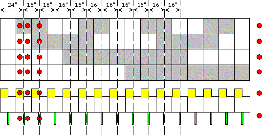
There is a way to do this using Grey Code and a specially designed flag.

3f65cfe00a88b669.gif


This actually describes more stop points than you are asking for. That is not a problem.

However, there seems to be some problems with your numbers...

16-feet of travel covers only 10-2/3 18-inch segments...

You indicate that you are looking for more than 10-2/3 stop & strap points.

A more complete description of your initial conditions (cylinder positions relative to the first strap position) and all subsequent moves would help a lot.

It appears that the last extention of the first cylinder provides only a partial index (6-inches)... the first move of the second cylinder would have to complete the index (12-inches).
 
Terry could you revamp that answer for a 16" travel? The items being strapped are hay bales, dont think many of those are 16 foot wide.
 
Gee Terry, how did you decide what color to use for your grey code matrix?... ;)

I understand the theory behind grey (gray?) code (only one bit changes), but I'm trying to think of an advantage to using it rather than plain ol' binary for this application... :unsure:

Is there one?... :confused:

beerchug

-Eric
 
Ron,
I was responding to Post #15. In Post #15, Timbo said...

I must stop my cylinders in many different spots is because I will have multiple straps spaced evenly accrossed my package. i.e.(move 18" then strap, move 18" then strap) I could only find one reasonable source for 8 foot long cylinders, and I have build a compound extension to get 16 feet of travel from my 8 foot cylinder. One must have 5 stopping positions plus full retract and full extend. The other must have 6 stopping positions plus full retract and full extend.

He called for 11 stop/strap positions spaced 18" apart - with some kind of sensor indication for each stop. Then he called for four additional sensors to indicate extended/retracted on each of two 8-foot cylinders.

I really don't think I'm too far off the mark.


Eric said,

What's nice is that you have a total of 7 positions, so 3 prox. switches is all you need.

Eric, I'm pretty sure... wait, let me check again... ... ... yep! I'm really sure that Timbo said he wanted to have 11 stop/strap positions in addition to Full Extended and Full Retracted indications for each cylinder. That sounds like 15 positions - some of those could be combined to reduce the position count a bit - not much.

Your plan can be applied twice - once for each cylinder - a total of 6 sensors. That will give Timbo the positions he asked for.

Eric also said...
Instead of trying to keep track of the cylinder's position by counting, it might be better to let the prox. switches give absolute position feedback.

A Prox watching for a flag can only tell you when the flag and prox are in close proximity. While between flags the system has no idea where it really is! There's no "absolute" position information in that! That method requires a certain amount of faith that things will operate as they should.

Let's see... I was at Prox-5 and I'm extending... so, I must be between Prox-5 and Prox-6 and heading toward Prox-6... maybe. I sure hope Prox-6 is there! That is not an "absolute" indication. That really seems more "faith-based" than "absolute"... don't ya think?

The first flag that I showed was "bait". It is actually one of two flags - and the second flag is actually two flags combined. The "Gray Code" flag (the first one) was for identifying the "segment". The grayed squares "were" all black. As such, the flag lost some of its detail. I used gray blocks with black lines so as to clearly identify the "block-segments" in the flag.

The second flag is used for "dialing in" the strap position.

3f679c9363b01764.gif


The first move on the far left might not be 24" - probably not.
Actually, the whole flag arrangement can be slid from one side to the other as necessary to "capture" the retracted and extended conditions.

The first flag can only identify a particular 18-inch segment (or is it a 16-inch segment? Timbo???). The prox's certainly can detect the transition-edge... but... while the prox is OFF, where is the strapper-head? And while the prox is ON, where is the strapper-head?

The second flag consists of two minor flag-types: "low/high" in a segment (yellow = low) and "dead-on" (green). While the prox sees the yellow flag and not the green flag, the system knows that it is in the lower section of the segment. As soon as the prox sees the green flag the system ignores the yellow flag and stops the cylinder. The system knows that the strapping-head is at the strapping position for Segment-X (identified by the Gray Code flag). If the strap-head happens to drift away from the strap position the yellow flag will indicate the direction of drift. Ya never know... that might be a handy piece of info to know!

This scheme works more like an "absolute" encoder. It allows the cylinders to be extended (or retracted if Timbo decides to use two-way processing) at controlled speeds. The strapper-head can leave a segment quickly, then when it sees the yellow flag, the cylinder can slow-down until the green flag is seen - then it stops, straps, and then moves on quickly to the next location.

This scheme uses 6 prox's. The "absolute" positions, relative to flag-edges, are known in this scheme as well as they are known in your scheme. However, this scheme also provides a broader sense of the "absolute" position plus a solid "relative" position - all without timers or counters.

The bottom line is, this system knows where the strapper-head is relative to any given strap position at any time - even on start-up!


So then, just to make my head feel like Goody's avatar looks, Timbo says this in Post #20...
My movement is spaced fairly evenly at 16" roughly in each move. Could I get away with four proxs on each ram? One for full extend, one for full retract to protect pump, valve, and hoses. Then the other two spaced at 16" with a sliding rod with flags. Move to prox 1 stop strap, move to prox 2 stop strap, move to prox 1 stop strap and so on.

Timbo... Didn't you say (in Post #15) that you want to have 11 strapping positions, and that you already had, and was therefore committed to using, 8-foot cylinders???

Of course, by this time, Timbo has probably already started a new thread with a nice little picture... oh, well...

I'm tired of editing... have at me!
 
How about.....

an Encoder. All you would have to do is find a place to mount it. Then find a place to make contact onto the shaft of the piston. Then all you have to do is figure out the counts per foot.

Then you could use the < or > comparators for stopping the hydraulics.

I have done something similar to this on a computer controlled welding machine that had to go at a certain rate for more than 30 ft.
 
Terry Woods said:
The grayed squares "were" all black. As such, the flag lost some of its detail. I used gray blocks with black lines so as to clearly identify the "block-segments" in the flag.
You took me too seriously, Terry... I was only having fun at the fact that you used GRAY (color) to show GRAY (code)... :D
"Absolute" was probably a bad term to use. What I meant by 'absolute' was that when you were AT one of the 5 (11?) positions, the position information would remain through a power cycle. No need to count flags or 'home' the system.

If you were 'mid-station' at powerup, a simple move forward or backward until you reached a station would let the PLC say "Okay, NOW I know where I am". Sort of like 'landmarks' for the PLC (keep driving 'til you see a Stuckey's on the left)

I read Timbo's post as a question whether to:

Use 1 switch and count flags to determine position (requiring 'Homing')
-or-
Use multiple switches, eliminating the counting and homing

I like your 'correct' use of absolute much better, but I don't know if Timbo has the ability to have flags running across multiple stations... :confused:

Time for Timbo to chime in and clear some things up (hopefully with a drawing!).

beerchug

-Eric
 
Sorry for all the problems I have caused. I am working on a drawing right now. It will be a simple drawing with a step by step explanation. I will start a new post hopefully tonight.
Thanks all
Timbo
 

Similar Topics

I am programming something that should be rather simple. But I have not programmed before and could use some help and guidance. I am using...
Replies
3
Views
1,772
Hey guys, was hoping someone could give me a bit of advice here in a couple spots. I'll start off with my dumb code and explain after...
Replies
10
Views
2,824
Hi, As my name suggests I'm new to the control systems space. I have a question regarding I/O for motor control. If I am using a SCADA pc to...
Replies
2
Views
1,663
I'm almost embarrassed to ask this, but why are there two L2N/VAC connections points on the 2080-LC10-12AWA device? Like I said, it's...
Replies
5
Views
2,011
I am an Intern with on 2 classes in PLCs. I need help on using one input to control six outputs. I need to press the pb one time for the first...
Replies
30
Views
9,247
Back
Top Bottom