rookie needs some help. system design

Here we go!
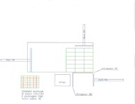
You are looking at a top view.
The bales are loaded into the machine with a loader in the 18 bale configuration you see in green. They are loaded 3 high, a total of 54 bales. You can only see 18. They are really loaded to the left and ram #1 has already extended and pushed the bales to the right. It then opens back up to create enough room to load another 54 bales while machine is strapping. Ram #1 is of no concern to me.
Now
Ram#2 extends 16", stops, strapper #1 straps.
Now
Ram#3 extends 18", stops, Strapper #2 straps.
Ram#3 extends 12", stops, strapper #2 straps.
Ram#3 extends 18", stops, returns to full retract.
Now the lifting section squeezes the 18 bale package and lifts it into the air 56". It is now waiting for the next package.
Now
Ram#2 extends 16" stops, strapper #1 straps.
Ram#2 extends 8" stops, returns to full retract
Now
Ram#3 extends 18", stops, Strapper #2 straps.
Ram#3 extends 12", stops, strapper #2 straps.
Ram#3 extends 18", stops and stays.
Now lifter unsqueezes package #1 and drops it onto package #2
Ram#3 extends to full extend, stops, returns to full retract. This pushes the 2 packages clear of the lifting section.
The process continues as long as there are bales in the machine.

I hope this sheds some light. I should have started with this drawing and explanation. Prox's, encoder, cable transducer?
You guys tell me now what the best would be considering I have already built the rams.
One last thing, all measurements above are full movement from a compound ram. I will probably mount devices in association with the cylinders. Divide all numbers in half to get actual cylinder ram movement.
 
Excellent drawing!...

Now that we have a drawing, let's revisit the original post.

timbo4255 said:
I have 5 hydraulic cylinders, 2 automatic strapping machines, and a handful(8-10) of proximity sensors and microswitches. My problem is that I have only dealt with basic ladder logic in the past and it was only on/off, yes/no programming. There were no variable inputs. Now I must figure a way to stop my cylinders in many different locations, not just in or out. I have found cable pull transducers that I believe would work great for positioning cylinders, but I have no clue about how a plc understands a variable 4-20ma signal. I have not purchased any sensors, hydraulic valves, or a plc yet. Could anyone please help me choose the appropriate plc, transducers, and sensors for this project. Any suggestions or ideas would be greatly appreciated Remember, you are dealing with a college educated, yet dumb farmer.

Those "cable pull transducers" are sounding more and more like the way to go. I doubt they'd be any less reliable than a bunch of prox. switches and their associated cables. Possibly a lot easier to troubleshoot as well... :confused:

Wire those 2 cable pull transducers into a PLC, and you're all set. We'll be more than happy to help you get the analog stuff sorted out if you decide to go that way. For under US$300 you can get a PLC (with analog inputs) that will operate on 12-24VDC (you ain't planning on plugging this machine into a wall socket, are you?).

By the way, you haven't caused any 'problems' around here. We thrive on confusion... :cool:

beerchug

-Eric
 
This unit will have 110 volt AC power. My strappers operate on 110.
It will be stationary when being used, but will still be mobile. When I am close to power I will plug it in, but when I am in BFE it will be ran via generator. The main base unit is actually built on a 10' x 22' gooseneck trailer.
 
I agree with Eric about the cable pull transducers. If you are worried about robustness, you could use an encoder driven by a rack and pinion. The rack runs the length of your stroke.
 
caps00us said:
You wouldn't need to place a rack on the ram.

Mount the encoder on a stationary part. Use a rubber wheel to make contact with the ram.

My only concern with this approach is that the encoder wheel may build up with **** (possibly literally?) over time. You're relying on the circumference of the wheel for distance measurement. If the circumference grows, your measured distance decreases... utoh

beerchug

-Eric
 
:rolleyes: AS I SEE IT, YOU HAVE SEVERAL OPTIONS TO TACKLE THE SUBJECT.
ONE ENCODER THAT I THINK WILL WORK JUST FINE IN YOUR PROJECT IS THE ONE COUPLED INTO A "SPROCKET"-THOSE USED IN BICYCLES. MOUNT IT IN A PLACE WHERE ITS TEETH TOUCHES THE PRODUCT ALWAYS THUS IF THE PRODUCT MOVES THE SPROCKET WHEEL TURNS. THIS CAN USSUALLY BE BUILT STURDY ENOUGH FOR YOUR KIND OF APPLICATION.
LIMIT SWITCHES HAS TO BE INSTALLED FOR SENSING THE FULL EXTENSION AND FULL RETRACTION OF THE HYDRAULIC CYLINDERS. THIS IS TO INITIALIZE THE POSITION OF THE CYLINDERS IN CASE THEY STOP IN THE MIDDLE IN A BLOCKOUT.
IN THE ABOVE CONFIGURATION, YOU'LL NEED A PLC TO CONTROL YOUR SYSTEM.
ANOTHER WAY TO DO IT IS;
NO PLC BUT LIMIT SWITCHES TO DO THE WHOLE POSITIONING.
FULL RETRACTIONS AND EXTENSIONS WILL HAVE EACH.THE POSITIONING WILL BE IN A WAY THAT A SINGLE LIMIT SWITCH IS ATTACHED IN THE MOVING PRODUCT OR ON THE CYLINDER HEAD AND FIXED METAL OBJECTS HAS TO BE INSTALLED IN THOSE POSITIONS NEEDED FOR "WRAPPING" TO ENERGISED THE SINGLE LIMIT SWITCH SO THAT APPROPRIATE ACTION WILL BE DONE BY THE RELAY CONTROLLED CONTROL SYSTEM.

I HOPE THIS HELPS.
 

Similar Topics

I am programming something that should be rather simple. But I have not programmed before and could use some help and guidance. I am using...
Replies
3
Views
1,771
Hey guys, was hoping someone could give me a bit of advice here in a couple spots. I'll start off with my dumb code and explain after...
Replies
10
Views
2,823
Hi, As my name suggests I'm new to the control systems space. I have a question regarding I/O for motor control. If I am using a SCADA pc to...
Replies
2
Views
1,663
I'm almost embarrassed to ask this, but why are there two L2N/VAC connections points on the 2080-LC10-12AWA device? Like I said, it's...
Replies
5
Views
2,010
I am an Intern with on 2 classes in PLCs. I need help on using one input to control six outputs. I need to press the pb one time for the first...
Replies
30
Views
9,246
Back
Top Bottom