SLC 5/05 SQO Instruction

eight_bools

Lifetime Supporting Member
Join Date
Apr 2019
Location
Oklahoma
Posts
71
I am working on a machine that is using the SQO instruction to step through a cycle, but I am getting lost following it. I have not worked with SQO instruction before but watched a couple video explanations and think I understand how they work.

What I am seeing is that as the machine steps through from 0 (stopped) to 8 (reset) it does not use any odd numbered steps. Does the SQO skip odd numbers or something?

I attached a copy of the program, there are several sequences and they are mostly all the same. The one that I am specifically looking at is the logic in file 6.
 
I have not looked at your program but it sounds like you are getting a double pulse on the enable. I use SQO all the time and they will step once on every false to true transition. So either your getting a double false/true or it will step if true and you unlatch the enable bit.
 
Actually the SQO would have to step through each number, and does here.


On 6:2 through 10 it checks the value of the control register for 0 through 8,


If you are only seeing positive values while monitoring then it might be the odd values are "Completed" steps and only active one scan - if you watched online you might have to watch a while to see a quick flick of an odd number once.


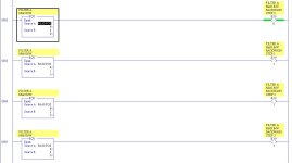
To test things like this I put in 'traps' where I latch an unused bit if the condition I am trying to troubleshoot goes true, see the second pic as an example. In this rung if the register ever equals 1 then my bit will be latched on.

Capture.JPG Capture2.JPG
 
Another item to keep in mind is nested branches take extra instructions and CPU clicks each scan.


If the extra BST and BND's were removed to make one extended branch the scan time of the program will improve, and depending on how many times branches are nested instead of extended it could make a noticeable difference. And with a smaller memory CPU it could save quite a few memory words if you had a large program.

Modified.JPG Original Nested.JPG Original Instructions.JPG
 
Actually the SQO would have to step through each number, and does here.


On 6:2 through 10 it checks the value of the control register for 0 through 8,


If you are only seeing positive values while monitoring then it might be the odd values are "Completed" steps and only active one scan - if you watched online you might have to watch a while to see a quick flick of an odd number once.


To test things like this I put in 'traps' where I latch an unused bit if the condition I am trying to troubleshoot goes true, see the second pic as an example. In this rung if the register ever equals 1 then my bit will be latched on.

Thanks I Automation

I have not been online to monitor while the sequence is used, I am just trying to understand the process. Currently working on installing an HMI that will monitor the process, which only happens once a week at between night and day shifts.

I can see how it transitions from 0 to 1 but do not see how it transitions from 1 to 2. I don't see any logic to go from odd to even.

On 6:3 I see an EQU to turn on B3:9/1 (Step 1), but that bit isn't used anywhere that I can see nor does it step the SQO in 6:1


NVM, I see what I was missing, B3:9/12 stays latched in 6:0 and the sequencer pulse timer steps the bits. Just had to hold my tongue out a little harder.


One other question though is in the videos I watched the SQO mask is usually a word from a file, in this case it looks like it is a HEX number. Any insights into why that would be? Maybe I am just not understating the instruction well enough yet.
 
Last edited:
I attached a PDF of ladder 6, the PDF for the project exceeded the forum's file size limit.


As far as using a direct mask as this program does or a data file mask can be a matter of personal preference of the programmer, and it also can be that the mask is not changeable except by online editing.


The value in a data file can be changed by an HMI Bubba, on 3rd shift, reprograms to change that value, or online just by entering a new value into the word - even accidentally in Run mode. The direct value can't be changed except though an online edit in Program or Remote mode.


When the rung with the SQO goes False the input bit resets and the next time it goes True it counts up to the next step, this would usually be by the timer pulse but could be by the conditions on the branches..
 
Last edited:
So based on my visual interpretation it would seem that it would be jumping the even numbers and executing the odds. In reality it is executing each step. Remember that step #0 is essentially a startup position so we won't really consider that step. The normal sequence will go from step 1 - 8 and repeat.

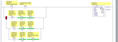
Looking at rung #1...

The top level of the branch will trigger a step every three seconds based on the sequence pulse timer. That would have it go from 1 to 2.

On the second level to the branch, this would make the XIC with B3:9/2 true (on the next scan) which would trigger it to jump to step 3. That would appear to happen immediately. Watching the position value it would appear to jump from 1 to 3.

Then after the three seconds have again transpired, it would execute step 4. The third level of the branch would then immediately have it jump to step 5. Again it would appear to jump from 3 to 5.

Repeat that for the remaining steps.

So to me, it looks like it would be going from Step 1 to 3, then to 5, then to 7. Steps 2, 4, 6 would be executing for just one scan so we wouldn't "see them".

That's my quick take.

OG
 
That's my quick take.

OG


Mine too, but I was figuring he was watching it online, then you might once in a while see the even number if it was even the one scan the CPU reported that value to RSLogix500, but it would only be for a flash.


Watching the value on a HMI you might never see the even value.


EDIT: SLC's don't use Studio5K, sorry.
 
Last edited:
On the second level to the branch, this would make the XIC with B3:9/2 true (on the next scan) which would trigger it to jump to step 3. That would appear to happen immediately. Watching the position value it would appear to jump from 1 to 3.


Walk me through this, because I read it differently:

If the top branch of Rung 0001 goes True (rising edge) from the timer pulse when .POS=1, I agree that will trigger the SQO and .POS will increment to 2, which would assign a 1 to B3:9/2 on the same scan (Rung 0004). Let's assume the B3:2/1 pulse goes back to 0 and the C5:19/DN is 0. On the next and subsequent scans B3:9/2 is now 1, so the input rung to the SQO would be True, but it was already True from that first scan (when .POS incremented from 1 to 2), so the SQO would be seeing a constant True on its input rung, and not a rising edge, across those scans, so it should not bump to 3 until some time after C5:19/DN becomes 1, when the middle XIO drops that second branch back to False, re-arming the rising edge detector.

There is definitely something not right on Rung 0001: on the branches that start with [XIC B3:9/[N]], for N = 2, 4, and 6, the final [XIO B3:9/[N+2]] will always evaluate True when their corresponding leading XICs evaluate True, because B3:9/[N+2] cannot become 1 until at least one scan after B3:9/[N] becomes 0, so those final XIOs are redundant.

One way to debug this might be to count rising edges of R4:60/EN.
 
You are right in the procedure. It will stop on position 2 and wait 15 minutes for the timer and counter to finish before triggering position 3. Then after it triggers position 3 it will immediately trigger position 4. Then we wait another 3 minutes (different timer and counter) for steps 4 and five to execute. Then we wait five minutes, and we get positions 6 and 7. Then it resets and it all starts over. I loaded it into RSEmulate and watched it go through the steps. I even turned down the priority setting to slow it down. It does work, I just don't know if it is working the way it is supposed to.

It is definitely executing the odd steps. It is just happening so fast we can't see it.

OG
 
Last edited:
In an earlier post (Post #8), OG said it would go from 1 to 2, and then immediately, i.e. on the next scan, it would go from 2 to three, i.e. it would appear to jump from 1 to 3:
(on the next scan) which would trigger it to jump to step 3. That would appear to happen immediately. Watching the position value it would appear to jump from 1 to 3.
Now in this latest post, OG is saying it will appear to jump from 2 to 4.

... It will stop on position 2 and wait 15 minutes for the timer and counter to finish before triggering position 3. Then after it triggers position 3 it will immediately trigger position 4.

I feel like I am looking at a different program (I know I am not seeing the whole thing in the PDF, but still ...).

I am pretty sure that R6:60.POS cannot jump two increments in two successive scans, unless R6:60/EN is being unlatched somewhere, because the SQO acts on a rising edge only (cf. this link). And once the second branch [XIC B3:9/2 XIO C5:19/DN XIO B3:9/4] of Rung 0001 evaluates to True because B3:9/2 became 1 on Rung 0004 after .POS became 2 on the previous scan, which happened on that previous scan after the top rung triggered the SQO that increments .POS to 2, the SQO should not see a False input rung, and thus cannot increment .POS to 3, until C5:19/DN becomes 1 (assuming C4:19 was reset in the first place). Barring double-destructive instruction or Latched/Unlatches I don't know about, that trailing [XIO B3:9/4] on that branch is still a canard.

And now you say RSEmulate acts just like you read it. What am I missing?

Thoroughly confused, thanks for your patience.

The penny drops? => Is this an April Fool's thing? I am always slow to pick up on that, so doing it to me, while I certainly appreciate the effort and the humor, is like shooting fish in a barrel.
 
Last edited:
Also, the [XIO B3:9/8] is one of several Stop conditions in the Start/Stop Circuit pattern on Rung 0000, which means this backwash cycle should be a once-through, and not repeat* until the Start condition (inputs I:1/9 and I:1/8), evaluates to True again.


* because B3:9/12 will be 0, effectively disabling all rising edges to the SQO.


What am I missing?
 
So the key in my earlier statement was that it would "appear" to jump from 2 to 4. That was because step 3 was transitioning too fast to see. But it was executing step 3. My apologies, I guess I was not clear in how I worded that.

Watching it running in the emulator...after toggling Start PB

  • SQO goes from POS 0 to 1 after the B3:2/1 turns on at 3 seconds. Important, this three-second timer is free-running and continues cycling even after this step completes. So it could turn on instantly, or up to three seconds later. Just depends on where the timer is in the cycle when you press Start.
  • On the next scan B3:2/1 turns back off so the SQO rung is now logically false. The timer in LAD 4 resets, causing the bit to turn off.
  • After the next three second interval, we move to POS 2. The top level and second level branches are now true. The maximum delay is three seconds but again, it can be less because the timer is free-running.
  • On the next scan, the top level is false, but the second level remains true for 15 minutes. POS remains at 2 for that duration
  • When the counter reaches 15 minutes the second level of the branch goes false making the SQO false
  • After the next "three second interval", we move to POS 3.

Repeat for the remaining steps.

And I had the Start PB toggled on, so when it is done, it resets and starts over. With a real PB it would have stopped and waited to be restarted.

So what I see is that the odd steps can execute for up to three seconds. But the free-running timer being used at the top level branch could cause the time between steps to be less than three seconds. But the longest any of the odd steps will run is three seconds.

Definitely a very odd arrangement of logic. But I'm sure to the programmer it is clear as day.

OG
 
@OG thanks, we agree now.

It must spend ~3s, i.e. the time between successive B3:2/1 rising edges, at each odd value of .POS. A duration of 3s is a bit long to say it "appears to jump,", but yeah, it would be quick, especially if one were watching an HMI.

And each even .POS value, greater than 1, will hold for some number of minutes (plus 0-3s), per the various counters:

  • 15 for .POS=2 (C5:19; T4:19; Rung 0012);
  • 3 for .POS=4 (C5:20; T4:20; Rung 0015);
  • 5 for .POS=6 (C5:21; T4:21; Rung 0018).
I would guess the reason for the 3s delay at odd values of .POS values to ensure certain combinations of the output-driven devices' physical states do not occur. This is a backwash process, so they may need to ensure e.g. one fluid does not end up in another fluid's pipework, i.e. ensure Valve A has time to close before opening Valve B.
 

Similar Topics

I am converting an old SLC 150 program to be used with a newer SLC 5/05. I have done this with other 150s, but I have some instructions that I am...
Replies
6
Views
8,338
I have a program that I've used 100 times. SQO settings: File N7:0, Mask 0FFFFh, Dest B3:1, Control R6:0, Length 8, Pos 2. Length & Position...
Replies
48
Views
975
I am building a traffic light simulator that I will be using to demonstrate PLC's at my sons' 5th grade elementary school as part of their STEM...
Replies
1
Views
1,756
Can you guys help me understand how the sequencer (SQO) on this program works, please. I see several files that are associated and then I see...
Replies
8
Views
2,718
Can anyone give me an example of using the SQO and SQC functions together Example 2 Pneumatic cylinders Cyl A ext Cyl B extend Cyl B retract Cyl...
Replies
2
Views
3,748
Back
Top Bottom