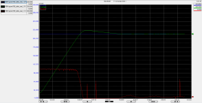
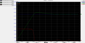
Thermocouple not steady values

Join Date
Jul 2021
Location
Bulgaria
Posts
51
Hi,

We have an ongoing project with a lot of thermocouple involved that monitor the temperature of heaters. There are more than 20 PID controllers in the system.

The controller is L33ER with WAGO EthernetIP coupler. The analog input modules on the couplers are 750-498.

There is an Add-On Instruction for the thermocouple analog input modules that are used in the controller logic.

The problem is that 4 of the thermocouple give values with extremely high amplitude i.e. let us assume that the setpoint for the PID is 300.0 degrees Celsius. When the PID is enabled and it is responsible for controlling the temperature the value from the thermocouple starts increasing with a step of 2-3 degrees Celsius. But the value from time to time becomes 300 - 500 degrees Celsius and then goes back to where it was according to the PID controller. When the value is above the setpoint, as expected, the PID shuts to control output and then when it is below, again there is 100 percent output on the PID.

Once the temperature is at steady state there no such overshoots on the temperature value.

All of the other thermocouples work fine. All of the thermocouples are type J. The 4 sensors I am talking about above are integrated in the heater itself and cannot be checked unless the heater is disassembled but the dealer sold them to us as heaters with integrated thermocouple type J.

The reason for this overshoot that we suspect is perhaps the integrated thermocouples are not of type J.

What do you think could be the reason for the behavior and is there are a way to check the type of the thermocouples without disassembling the heaters?

Best Regards
Konstantin Kolev
 
When thermocouples are placed in an kiln, they are placed in the cavity where the product to be heated is, not in the heating resistances where there will always be a much greater temperature oscillation.

I think you would have to discard those thermocouples built into the heater and, for those regulations, place others similar to the ones that work well.
 
When the PID is enabled and it is responsible for controlling the temperature the value from the thermocouple starts increasing with a step of 2-3 degrees Celsius. But the value from time to time becomes 300 - 500 degrees Celsius and then goes back to where it was according to the PID controller. When the value is above the setpoint, as expected, the PID shuts to control output and then when it is below, again there is 100 percent output on the PID.
Sounds to me as your PID parameters are not adjusted correctly.

Once the temperature is at steady state there no such overshoots on the temperature value.
At least your PID is not totally unstable.
 
When thermocouples are placed in an kiln, they are placed in the cavity where the product to be heated is, not in the heating resistances where there will always be a much greater temperature oscillation.

I think you would have to discard those thermocouples built into the heater and, for those regulations, place others similar to the ones that work well.


This is a plausible explanation.

Can the OP provide trends of the SP (setpoint), PV (Process Value i.e. temperature), and CV (Current Value i.e. output) of the PID?

Also, is the PID CV output run through a time-proportioning (or PWM) controller to turn the elements on and off? What is the frequency of the cycle?
 
The reason for this overshoot that we suspect is perhaps the integrated thermocouples are not of type J.
The type of a thermocouple refers mainly to the temperature range it is is suited for. If the sensor is directly exposed to media, there may be issues with the metals used being reactive with the media. I am guessing it is not the issue here.
J type is suitable up to 760°C.
All thermocouples have a relatively fast response.

I think you would have to discard those thermocouples built into the heater and, for those regulations, place others similar to the ones that work well.
This is a plausible explanation.
I dont think so.
(edited) The concern of the OP is that he sees large temperature overshoots, which he think is caused by slow reaction of the thermocouple. But TC's are by principle very fast. Signal delay is because there is something restricting the transfer of heat energy to the TC, i.e. the walls of a sensor pocket. Changing the TC to another type will not change that.

Even if there is a delay in the signal because of the walls of the pocket in which the thermocouple is installed, is this delay significant when compared to the process delays, i.e. the delay of the active heating elements, and the delay of the heating of the media itself ?
If this is actually the case, it would be a serious design flaw of the heater. I am guessing this is a standard design, so I don't think so.

Explain more about the process.
Explain why you think changing the thermocouple type would make a difference.

I would focus on the PID.
 
Last edited:
1.
thermocouple involved that monitor the temperature of heaters.
Are you sure that the thermocouple is measuring the heater temperature?


It's more typical to measure the heaters are heating, air, water, some blend of liquids, whatever, than it is to measure the heater temperature.

2. A wrong type thermocouple will give the wrong absolute temperature values because its mV output will be misinterpreted by the controller.


But the PID doesn't know that, so the PID will attempt to control to a value that isn't the real temperature. The end result of proper PID with the wrong thermocouple type would be steady control at setpoint but the actual temperature is not the correct temperature, either too low or too high, depending what the substituted type of thermocouple is.

3. All PID needs to be tuned, to match the magnitude of the controller's output to size of the error.

The description of the problem sounds to me like tuning that is too aggressive. Once the tuning it backed off and gets to steady state, then you can see if the temperature matches what the displayed value is. But I think it's unlikely that the vendor put in the wrong type thermocouples.
 
The problem as stated in the first post sounds to me like electrical noise, or possibly a loose wire on the thermocouple signal wire rather than an issue with PID tuning. The OP should check for good shielding and tight connections in the wire from the built-in thermocouples. I mention a loose wire because the typical open-wire response in a PID controller configured for a heating application is "Fail high".
It is almost certainly not a case of a discrepancy between the type of thermocouple configured in the PID controller and what is actually connected.
 
He writes that he sees an overshoot up to 500 degr.C above the setpoint of 300 degr.C, but eventually it settles at the setpoint. That does not sound as noise to me.

KonstantinKolev said:
When the value is above the setpoint, as expected, the PID shuts to control output and then when it is below, again there is 100 percent output on the PID.
Looks to me as if the PID gains are simply too high.
edit: and/or lack of anti-reset wind-up.

edit:
This one tells me that when the PID is not controlling the temperature, the values from the thermocouple are stable (he describes how enabling the PID starts the unusual situation resulting in the overshoot):
KonstantinKolev said:
When the PID is enabled and it is responsible for controlling the temperature the value from the thermocouple starts increasing with a step of 2-3 degrees Celsius.
 
Last edited:
I wont rule out that there is some kind of noise feedback from when the heating elements activates.
That could explain why when the temperature is settled, the temperature hikes do not appear.
 
When the PID is enabled and it is responsible for controlling the temperature the value from the thermocouple starts increasing with a step of 2-3 degrees Celsius. But the value from time to time becomes 300 - 500 degrees Celsius and then goes back to where it was according to the PID controller.
Unfortunately, the OP didn't offer any hint as to the duration of the high temperature readings. I interpreted his statement to indicate short duration. JesperMP apparently interpreted it as a longer duration overshoot.
 
Unfortunately, the OP didn't offer any hint as to the duration of the high temperature readings. I interpreted his statement to indicate short duration. JesperMP apparently interpreted it as a longer duration overshoot.
+1
If the OP could describe his process a bit more, and this:
Can the OP provide trends of the SP (setpoint), PV (Process Value i.e. temperature), and CV (Current Value i.e. output) of the PID?
 
Thermocouples measure the mean temperature of the bimetallic bead. Full stop.


Whether the temperature of a bead is representative of the bulk temperature of the device OP wants to control is unknown.


What I thought @lfe was suggesting was that the thermocouple bead might to close to the actual heating element, which will generate big, and transient, spikes in the bead if the PID output is feeding a time-proportioning and/or PWM heating scheme, and so the measured reading is not representative of the bulk temperature that OP wants to control. During the time the heating element is off (again, assuming PWM), the element and the bead would quickly equilibrate to the bulk temperature of the device, which is consistent with the behavior OP describes. OP said the system hits a steady state; while that may suggest that this model is not the case, the heating element will be on for shorter periods so any spikes would be shorter and have less amplitude and so would look more like steady state. A lot depends on the frequency of the PWM cycle and the mass (thermal inertia) of the device being heated.

Other noise sources, like dodgy wiring, are certainly another possibility.

We don't really know enough and at this point everyone is offering ideas, probably based on their own experience.

[update: see item (iii) in my signature; it looks like @JesperMP suggested the same thing in post #10]
 
Last edited:
Hi,

I appreciate all of the opinions above.

Let me give a bit more light about what the application is. The machine is a Bag in Box machine and the particular heaters that we are troubleshooting are for sealing the gland

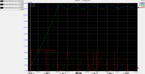
According to me, now this weird behavior of the thermocouples disappeared for some reason. I did a heating up procedure couple of times in the last day and as the trends show it seems fine.

After the PIDE block there is a SRTP block that controls the output.

Attached you can find trends for each of the heaters and the function block diagram of the PIDE.

Best Regards
Konstantin Kolev
Gland Seal 1.png Gland Seal 2.png Gland Seal 3.png Gland Seal 4.png PIDE.png
 
Last edited:
The red line is probably the heating action. No description of how the heating action actually works.
All 4 trends shows some odd spikes in the red line.

Gland_seal_4 is unstable. Reduce the PID gains.
 

Similar Topics

I am having an issue getting a IY4 to read my thermocouple correctly. We have a R type and K type hooked up and sitting at a known room...
Replies
5
Views
533
Posted by u/mr_biodtox 44 minutes ago Delta ISPSoft - Establishing communication with thermocouple module Hi, How do I establish communication...
Replies
1
Views
339
Hello. PLC beginner here, so apologies in advance for any incorrect terminology or poor communication. I have an SLC 500 Thermocouple/mV Analog...
Replies
1
Views
651
Hello Guys, Trying to scale a thermocouple directly into my IY4 card. Connected into the terminal +\-. I’ve scaled the range of my J type to...
Replies
4
Views
1,672
Hello I have a project to record temperature from thermocouple and store it to memory card, the problem is my client didn't provide new...
Replies
11
Views
2,950
Back
Top Bottom