Wiring in a 4-20ma Sink Flowmeter into a 1734-IE4C

lunenburger

Member
Join Date
Jul 2008
Location
Summerside
Posts
209
Just wondering if it is possible to wire in a Cynergy UF08B100 Flowmeter into an Allen Bradley 1734-IE4C.

I have tried every way I can think of and I either get 21ma or 0ma.

Here is the link to the install manual for the Cynergy flowmeter

https://www.cynergy3.com/sites/default/files/blog-documents/UF%20install%202019.pdf

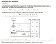
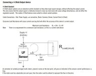
And I have attached a picture of the wiring diagram for both the 1734-IE4C and flowmeter

I believe the Analog input card can't do sinking input, so I think I may have to source another card....

inp.jpg trans.jpg
 
Hmm Red to +24V black to 0VDC and brown to Input on the card doesn't give you anything do you have a common landed on the card from your power supply as well?

The card should be able to handle the sensor. Are you reading these mA with a voltmeter in series with the sensor or from the PLC?
 
The common from the 24v power supply is jumpered internally from the 1734-TOP3 module.
I am looking at the analog input values in the PLC. I don't have my mA multimeter with me here, only my amp meter...
 
The attached image is how I have the transmitter wired...
I am measuring 20ma on the channel with no flow ( I would think it should be 4ma)
Is there something in the configuration of the 1734-IE4C that I am missing??

wired.jpg
 
I feel like it should be red connected to +24VDC off the power supply and Brown to the input. You could check the scaling and alarms in the tabs.
 
I agree, but I get 0v and 0ma when the brown wire is on channel 0....
the words sinking 4-20ma signal make me nervous... I feel the card won't do it
 
The card is basically the same as the 2 channel only it doesn't provide a spot to land 24V locally. Sinking is what you are doing when the card provides a grounded common, vs Sourcing providing a voltage common Right? I would try and hunt down a meter that you can put in series and test with flow established etc.

All status lights are good, no yellow boxes next to the card in the tree etc?
 
Do you have a loop calibrator? When I run into this sort of confusion, I drive the device with my Fluke 707 loop calibrator to verify that I understand where the wires should go. That meter can measure the current loop and supply loop power at the same time which is really handy.
 
lunenburger said:
The attached image is how I have the transmitter wired...

1734-IE4C%20-%20UF08%20%28lunenberger%20wiring%29.jpg


Try wiring it this way instead?...

1734-IE4C%20-%20UF08.jpg


Regards,
George
 
That was how I had it wired originally...
At least with the brown wire landed on the channel 0 terminal, the flowmeter has a flashing light that shows flow, it's just there is no signal coming back to the input card.
 
Nope, the two devices aren't compatible.
The easiest solution is a 1734sc-IF4U which you can get from your Rockwell distributor.
1734-IE4C is just a resistor between C and In0.
If it must be the 1734-IE4C, then you will need a signal isolator between the devices. Might be a good idea to add an isolator anyway if it's out in the field.
Another option is to change the flow meter...
Ian
 
You are correct Ian, I am going to go with a 1769-IF4 and go with the 0-5v option on the flowmeter. At least I know that one works, as we already have one setup.
I also tried our Fluke 725 process meter to try and get it working but had no success.

After emailing Cynergy tech support, they said...
"We do not have any data on systems this works on"
So I take that as they are not sure if the analog output actually works...
 

Similar Topics

Hi All, I have a question about the input wiring on a HMISCU8B5. I am so close to having what I am after yet it seems so far away. I have...
Replies
34
Views
7,187
Ok, so I have 2 boxes with separate power supplies they are going to be about 300 to 400ft apart. the Main Box as the PLC in it with the Analog...
Replies
19
Views
5,370
I have 15 signals that are going from signal conditioner to PLC Input module. They are all 4-20mA and there is nothing else in the wireway...
Replies
23
Views
5,513
Hi guys, I have a Metler Toledo M800 that will be used to read mainly my ph and conductivity sensor on my system, i saw on the terminal block i...
Replies
1
Views
1,690
Hello, I have a float switch that is labeled as below and has only 2 wires (red,black): Input 10-30VDC Output 4-20mA Resolution 5mm I am...
Replies
11
Views
3,334
Back
Top Bottom