Flashing Bits and non-flashing output - RSlogix

mitureg

Member
Join Date
May 2013
Location
Canada
Posts
199
Hello there, Sorry I am quite new to this... thank you for taking the time to answer my thread.

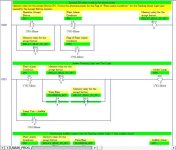
I have a small problem trying to get an output light flashing prior to pressing an operator ACCEPT button IP1.

The output Amber Light needs to flash when the "Plant Alarm Condition" arise, but stop when the Operator Accept Button IP1 is pressed.

Is this the correct way of programming a flasher?
The problem is that the output keep flashing even when the Accept Button is pressed (!)

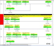
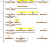
There is several instance of the Amber Light output OP0 within the rungs (see the second image). I think it might have something to do with my problem.

The same output is activated in one rung while in the other rung it is not (!), hence probably causing the output to flash as an indicator of that??

Is there any solution, is this a design mistake?

Many thanks!

Annunciator3b.jpg Annunciator3d.jpg
 
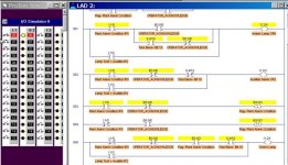
Get rid of the double-coil syndrome. Normally any one Output should appear only one time in any program. You will like this method much better because it works.

Notice that your Operator Accept Button MUST be a maintained-contact type (stays ON when pressed ON), otherwise this logic will not work. If your button is a momentary-contact type (only ON while pressed), then you will need to add a rung for an Internal B3 relay to seal-in your button press, and use the new B3 in place of the Accept Button on both rungs.

Mitureg's Flashing Bits.JPG
 
Last edited:
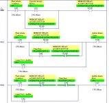
Hi Lancie, thank you for your help. Much appreciated. I did the modification adding a B3 seal-in for the press button. Did I do it correctly... any thoughts?

I also have a latch/unlatch as well for a "Flag". I am not too sure if it would be preferable to use a B3 for that one too.

Does everything look acceptable?

Regards,
Alex

Here's the full program in 2 posts.

Annunciator4a.jpg
 
Does everything look acceptable?
Your new version seems to work okay - if your I:0/1 is connected to a momentary-contact pushbutton.

Here is the way a typical industrial plant alarm signal works:
1. Alarm input signal goes ON.
2. Alarm Horn and Light goes on (red flashing usually).
3. Operator on duty hears horn or sees light, rushes to operator panel, determines what is causing the alarm, takes action if needed, then presses the "Alarm Acknowledge" button.
4. On pressing the Acknowledge button, the alarm horn goes OFF, but the Alarm Light changes from flashing to steady ON. The Alarm Light stays on until the alarm input signal goes OFF.

Note that based on step 4, you do not need a flag to reset your alarm condition, but only use the alarm input signal to reset the alarm acknowledge relay. I would do it like the attached picture:

Mitureg's Flashing Bits-R2.jpg
 
Last edited:
Hi Lancie, thank you for your reply, it's always nice to hear from you.

Note that based on step 4, you do not need a flag to reset your alarm condition, but only use the alarm input signal to reset the alarm acknowledge relay. I would do it like the attached picture:

I understand. The only output that wont work properly if I do not have a flag is the Flashing Green Light.

This light comes up when the Plant Alarm Condition went up, then down again before the operator had time to rush to the control panel and figure out what happened. He then hit the Accept Button and the Flashing Green Light goes OFF.

I've attached my complete program in attachment. I hope I didn't do any mistake again.

Much appreciated.
Cheers!
 
I will test your last program using the LogixPro Simulator. Right away, I see a problem on Rungs 3 and 4. You have Latched and Unlatch INPUT I:0/3. I think that you probably meant this to be internal bit B3:0/3. Latching an Input bit will not do much for you.
 
Last edited:
After fixing the errors on Rungs 3 and 4 (using Outputs instead of Inputs), the next error to appear is that the Green Lamp cannot ever go on. Looking at Rung 005, the Green Light could only go on if the Plant Alarm Condition I:0/0 is OFF and Flag of Plant Alarm Condition I:0/3 is ON. But the Flag of Plant Alarm Condition can only be on when the Plant Alarm Condition is ON! It is a paradox, a connundrum.
co·nun·drum
/kəˈnəndrəm/
Noun
A confusing and difficult problem or question. A question asked for amusement, typically one with a pun in its answer; a riddle.
Synonyms

riddle - puzzle - enigma - mystery
The attached ZIP file is a copy of the LogixPro Simulator program that is running in the picture. For testing purposes, I changed the flashing bit to S:4/10 to allow time to make a screen picture with the bit ON.

At this point in the learning process, it is time for you to come clean and say exactly WHEN you want each of the lights to be on. I think your Green Lamp is merely an "Acknowledge" Indicator (signals that the operator has acknowledged the alarm condition). If that is what green means, then the fix is simple, and you don't need a lot of the fat in your program. The attached files are showing your last version, not the fix.
This light [Green Lamp] comes up when the Plant Alarm Condition went up, then down again before the operator had time to rush to the control panel and figure out what happened.
I cannot figure out what you mean by "then down again". It is a mystery. Are you saying that the Green Lamp should be controlled by a timer? (A timer is the only thing I could see that would allow it to come on then go off again before the operator does anything at all.)

Mitureg Annunicator-1C- LogixPro Simulator.jpg
 

Attachments

  • Mitureg's ANNUNCIATOR_IC.ZIP
    554 bytes · Views: 6
Last edited:
This light [Green Lamp] comes up when the Plant Alarm Condition went up, then down again before the operator had time to rush to the control panel and figure out what happened.
Do you mean that the Plant Alarm Condition is going on, then back off before the operator has time to see what condition caused the alarm? Do you then want to latch on a bit that shows the condition that caused the alarm? Perhaps you need to create an Alarm History file, and save all alarms as they occur. That is the usual way. Normally an alarm indicator and horn are not latched ON, because the hope is that the alarm condition goes away as soon as possible.
 
This light comes up when the Plant Alarm Condition went up, then down again before the operator had time to rush to the control panel and figure out what happened.

Clarifications: It's about the plant alarm condition going up and down, or I should have said the plant alarm condition occurs then cease before the operator had time to rush to the control panel.

When this happens, meaning after the plant alarm condition has occurred without the Accept Button being pressed while it was on; the Flashing Green Light will be on. The operator can now press the Accept Button, but this time to Turn Off that flashing green light.

Sorry for the confusion Lancie.

Cheers
 
When this happens, meaning after the plant alarm condition has occurred without the Accept Button being pressed while it was on; the Flashing Green Light will be on. The operator can now press the Accept Button, but this time to Turn Off that flashing green light.
How is the Alarm Green Lamp doing anything that the Alarm Amber light is not also doing or indicating? There seems to be something lacking or missing here.

If you simply want to record an alarm, then seal in (not latch) a flashing green light when the Plant Alarm Condition I:0/0 goes ON. Then unseal it when the Accept button is pressed. But wait! That is exactly how the Amber light now operates! Why have 2 lamps doing the exact same thing? You need to thing about this and figure out the job for each lamp, yellow and green, flashing and non-flashing.
 
This is the only way that the Green Lamp makes any sense for me. See attached working LogixPro version 1D. Green now stays on even if the alarm goes away, until operator presses the Accept button.

With the green light now doing essentially what the Amber Lamp was doing, now you could delete Amber (or replace Amber with Green or Green with Amber). Having 2 alarm lights for the same alarm point is redundant and inefficient.

The only thing accomplished with the green light is to force the operator to hit the Acccept button for every single alarm event, no matter if it goes away in a few seconds as most alarms do in a well-maintained system. If I were an operator I would be digging out the giant Operator All-Purpose Fixer Tool (10-lb sledge hammer) and do a little work on this dinky irritating system!

Mitureg Annunicator-1D- LogixPro Simulator.JPG
 
Last edited:
Hi Lancie, sorry we got confused. The amber light and green light do not have the same purpose.

Here is the problem description:

1. If the operator presses the ACCEPT button when the plant is in alarm,
the audible alarm stops and the flashing Amber light changes to
permanently ‘ON’.

2. If the plant drops out of the alarm condition before the ACCEPT button is
pressed, the panel will show a flashing Green light. The Audible alarm
and Amber light will go ‘OFF’.

3. If the ACCEPT button was pressed when the plant is healthy as in 2
above, the flashing Green light will go ‘OFF’.

4. There should be a LAMP TEST button which, when pressed, will light all
lamps and sound the audible alarm.

Cheers,
Alex
 

Similar Topics

I have a 1769-L24ER-BB1B and I am trying to flash it to 34xx, its flashing red and faulted, when I try to flash it I get a popup stating it needs...
Replies
14
Views
252
Hi Guys, I have a 1769-L24-QBFCB1 that has the OK light flashing on the embedded counter module. The manual states it is a resettable fault, but...
Replies
0
Views
104
Hello all. I have a remote that uses a 1734-AENTR series C. We had to change it to a new one and, after adjusting the IP and number of slots...
Replies
16
Views
535
Hello all! I have a 5069 -L310ers2 plc that has A1 and A2 Ethernet port. I connected to A1 port while flashing the plc and it was successful. The...
Replies
8
Views
253
Hi All, I am new here , I am trying to flash AB plc 5380 safety guard logix Freeware 32.012 which is our program and old plc, but It does accept...
Replies
11
Views
415
Back
Top Bottom