Counter (CTU) spontaneously resets - Expert opinion requested

sudden thought:

is there an OTE instruction for B3:4/9 anywhere in the program? ...

if there is, and IF (that's a big IF) the processor happened to transition into a "GO TO RUN" condition, then PRE-SCAN would have written a ZERO status into bit/box B3:4/9 – and this would have happened before the processor made it's first pass through the logic ... and it would have happened REGARDLESS of the logic (true or false) which normally controls the status of bit/box B3:4/9 ...

so ...

if the logic which normally controls bit/box B3:4/9 happens to be located AFTER the counter reset rung, then the XIO for B3:4/9 would have been evaluated as TRUE on the processor's first pass ...

this could account for an unexpected RESET of the Counter ...
Yes! There is an OTE and it's controlled by an old-fashioned rotary encoder (selector switch). I'm now wondering if the encoder is becoming intermittent.
 
That's not quite "fail-safe" functionality...
You are relying on a piece of hardware in the field to "energize" the B3:4/9 OTE and keep the logic from resetting the C5:0 accumulator!:unsure:
I'd verify the encoder and ensure the ladder logic will not reset the accumulator unless the encoder is functional.
 
Last edited:
I would start by determining (if possible) if the counter ran away and cycled through steps 21-100 in 40 scans of the program or did those steps never occur? I don't know if you have any means of determining that since it would happen quite fast. (would any of that get captured by another counter or data historian?)

If steps 21-100 never occurred, then the reset must have happened or the .ACC value was written to.

If the counter ran away, aside from the other comments already made, I would also question what B3:5/1 is doing in the HMI. Any chance that something caused it to flicker rapidly from the HMI? Is it coming from the HMI directly or is it controlled in the program via some sort of toggle logic. If so, I've seen toggle logic that seems to work flawlessly for a long time before suddenly seeing a glitch. When it does, that glitch can make the bit rapidly toggle every scan.
 
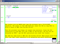
well, I can't say that the encoder didn't have anything to do with the problem – but here's some more detail on what I think COULD have caused the counter to unexpectedly reset – if the processor had been put through a "GO-TO-RUN" condition ...

basic idea:

to most people, the unconditional OTE instruction in rung 0002 should constantly keep a ONE status in bit/box B3:4/9 ...

so ...

to most people, the XIO instruction in rung 0001 should constantly be evaluated as FALSE ... so most people would assume that the counter will never be reset by the RES instruction ...

but ...

whenever the processor first goes into the RUN mode – the RES will be fired ONCE ... this will reset the counter ...

note that a GO-TO-RUN condition will occur after a power cycle – or by switching the processor from PROGRAM to RUN mode by any method ...

note that if rungs 0001 and 0002 were "swapped" in position, then the counter would NOT be reset at "GO-TO-RUN" ...

NOTE: that this is programmed this way as a demonstration of how PRE-SCAN can cause unexpected results ... this is NOT intended to be a demonstration of proper programming techniques ...

.


prescan_res.PNG
 
The XIO of the C5:0/CU will cause the count to increment every other scan as long as the RLO preceding it is true. I can't think of one single good reason to use the "CU" ahead of the counter unless you actually want to count scans. They have basically turned the counter into a timer. It is difficult to understand how this could ever have worked.
 
Last edited:
I second (or is it third?) the notion that the XIO of the counter's .CU bit should not be on the rung preceding the counter.

All it has the effect of achieving is exactly the way a counter works - namely that if the rung evaluates as true, the counter looks at the state of its .CU bit to determine if it should increment (.CU bit off), or not (.CU bit on), then it turns on the .CU bit.

Now, by having that conditional instruction on the rung, once the counter counts up, its .CU bit will be set.

On the next scan, .CU bit being set makes the rung false, thus making the CTU instruction false, so it turns off its .CU bit.

On the next scan (assuming the other conditions on the rung remain true), the counter determines that the rung has changed state from false to true, and will increment again.

So, IF the other logic conditions are held true, this counter will "run-away", incrementing every 2 scans.

This may have always been there, and the "other conditions" on the rung may have hidden this, IF they weren't held true for more than one scan.

If the OP can categorically say that this rung has not been changed, then I suspect that changes to the logic elsewhere may now be revealing this logic error.

I have always taught people the inner workings of instructions, i.e. how the processor uses the status bits in the control register - they are there for a reason, and understanding those reasons helps to prevent the sort of logical error that appears in this case.

I just went through recent archives and can confirm that the rung has not changed since November 27, 2009. It has worked fine, without exception, since then.
 
I would start by determining (if possible) if the counter ran away and cycled through steps 21-100 in 40 scans of the program or did those steps never occur? I don't know if you have any means of determining that since it would happen quite fast. (would any of that get captured by another counter or data historian?)

If steps 21-100 never occurred, then the reset must have happened or the .ACC value was written to.

If the counter ran away, aside from the other comments already made, I would also question what B3:5/1 is doing in the HMI. Any chance that something caused it to flicker rapidly from the HMI? Is it coming from the HMI directly or is it controlled in the program via some sort of toggle logic. If so, I've seen toggle logic that seems to work flawlessly for a long time before suddenly seeing a glitch. When it does, that glitch can make the bit rapidly toggle every scan.

B3:5/1 is a toggled "switch" from the HMI that allows the operator to "Pause" the cycle at any time. It just keeps the counter from counting up.
 
Should I simply replace the [XIO C5:0/CU] with an OSR?

Think about what you want to cause the counter to increment.

Note the fact that a false to true transition of the rung-in-conditions is required to trigger it, a fact you can use in your favor.

Maybe you want to absolutely limit the counter to one increment per second...you could add a TON in parallel with its TT bit branched around all else holding the CTU true for a minimum of one second.

I have no idea what modes of operation this counter needs to be able to control, but it might need a little extra protection against runaway, whether that be simply remove the XIO C.CU bit, or perhaps the addition of some other condition in series or parallel...

If a "double-bounce" of any of the logic to the left of the CTU will cause an erroneous increment, then ensure the resulting logic protects against that.

Sometimes a well placed oneshot is called for, but the counter instruction, by design, rarely needs one ahead of it.

EDIT: Let's take a look at what's going on in the snippet and make some assumptions...for the sake of discussion...not necessarily safe and valid suggestions without seeing the bigger picture.

attachment.php


1. Move the pause button to the RTO timer (if it's a TON, insert a RES rung right BEFORE it trigger by its DN bit, and switch it to RTO timer).

2. If we're in wash mode and my timer is greater than a variable with a zero in it? No, lets protect against a zero preset and make the timer at least have say 0.1 second on the clock before advancing. We can do this by copying and pasting that GEQ instruction and changing one copy compare address to the literal constant number. If we must use zero to skip steps, we need to skip them all right now, so do we loop? (yuck) or create a simpler method to skip steps, like shortening the sequence (adjust the Cx.PRE)?

3. Take all that other stuff out. If my timer's satisfied for that step, and I am still in that wash mode, advance (which assumedly also restarts the timer, but if it doesn't the CTU will stay true and not increment again).

If someone or something rapidly cycles the WASH mode, it still should not be able to trigger a runaway condition because the GEQ instruction should go false upon each increment of the CTU (in logic I assume is located elsewhere). EDIT: dropping out of WASH resets the Counter, so changing modes is already disallowed.
 
Last edited:

Similar Topics

Hi all, I'm newbie here to plctalk! I writing a PLC programm in ladder where I put an output bit to zero during 9s and the same output bit to one...
Replies
13
Views
6,853
Hi Guys, I have a 1769-L24-QBFCB1 that has the OK light flashing on the embedded counter module. The manual states it is a resettable fault, but...
Replies
0
Views
109
Hey Everyone, After reading a lot on this forum and elsewhere I see not many are fond of the 1794-VHSC module. I can see to a degree as I was...
Replies
3
Views
168
Hello Folks, Has anyone configured a Momentum high speed counter on Unity 13.1. We need the wiring diagram for Momentum High speed counter and...
Replies
0
Views
78
Hi all, I am working with an incremental encoder (ABZ signals, 360 ppr (so 1440 counts per rev)) to replace the existing "manual" encoder wheel I...
Replies
51
Views
2,628
Back
Top Bottom