FX3U clone problem getting analog input/output to work

eagl1

Member
Join Date
Aug 2023
Location
KSA
Posts
67
Hi,

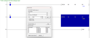
I tried today to get RD3A and WR3A instructions to work on the PLC and it didn't work, but it worked in simulation.

rd3a-wr3a.png


I followed the clone pin layout and applied several YouTube videos, but didn't work with me.

S7346e977c61e4f7db385346ca4390d15J.jpg_640x640q90.jpg


This is my today's setup:

20231225-091702.jpg


I also get this note message during programming the PLC, I don't know if it's a problem or not.

MELSOFT-Series-GX-Works2-Untitled-Project-PRG-Write-MAIN-3-Step-12-25-2023-11-06-04-AM.png
 
Last edited:
The simulator does not support analogues as there is no real analogue card what you are doing is just either forcing the D register, also from your screenshot you are using the same address of the analogue input & output these are seperate so you need to change the "D" numbers I understand you are just writing the value from the analogue input directly to the analogue output but suggest you make them different D registers ready for manipulation i.e. as shown, I'm taking an analogue input creating a simple PI control & then sending the manipulated value to the output, this was just to work as a heater control, it measures the PT100 temperature sensor & adjusts the output to control the temperature accurately.
 
Last edited:
Can you please provide me with a more simpler example ? I just want to know how to activate the analog input/output peripherals. Then I might proceed with more advanced programming.
 
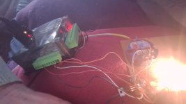
Here is a simple one just force a value into D2 to give an output on the analogue out, here is a simple pic of the clone working sorry about the quality but just had to point my pc at the board on the sofa, this is just a forced value to light the bulb via a power transistor & 0-10v from the plc.

Analogs.png clone_04_40_Pro.jpg
 
I don't know what to do ?! It didn't work at all ! I tried many examples from YouTube and your examples non worked.

20231226-145942.jpg


But the logics X-inputs and Y-outputs work fine.

I'm suspecting that there might be some internal settings that I haven't done.

These are pictures for the clone as I noticed that your clone has red leds where the one I have has green ones.

20231226-150149.jpg


20231226-150534.jpg
 
Where are those white leads going to from the analogue common ?
I don't think there are any settings, My board is transistor output where yours is relay & yes the power/run lights on mine are red the same as the input leds
 
Last edited:
They are going 3 stages of wiring for those screws :)

20231226-162434-resize-54.jpg


I took this picture while I was leaving the workshop so everything was switched off.
 
Here is a simple one just force a value into D2 to give an output on the analogue out

I want to know this point. I watched people do real time experiments on the PLC and get the readings on the simulation. I want to be sure is this correct ?

Do you mean that when I hit simulation, and the PLC is connected to the PC. Can I do in-circuit debugging ?

So, when you say I force a value into D2, do you mean that when the simulation is running, I can put a value in D2 and it must be activated in the PLC ?
 
I think you are getting confused between simulation & monitoring.
Simulation is where you do not use a real plc but use the in-built simulator, monitoring or often called going on-line directly to a real plc.
To use the simulator you select Debug then start/stop simulation this is just a simulation of a real plc but certain functions do not work like special cards or analogues high speed processing etc.
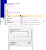
After you download your program you press the green triangle button on the menu this starts the monitor of the program so you can see what the status of the code is, to force a value into a register or turn bits on/off you right button click on it & a menu pops up select Debug then modify value & you can enter either a value for a register or force on/off a bit.
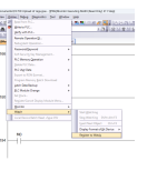
There is also one other way where you can bring up a window and enter many variables & press the green monitor key again & force values directly there.

pic 1.png pic2.png pic 4.png
 
I tried this simple program, where I set M0 then use Y0 as output, and tried to change M0 value but Y0 didn't switch ON/OFF on the real PLC.

monitor.png
 
It is probably because you seem to have the simulator tunning, it will be looking at the simulator, you cannot have both because the simulator forces GXW to ignore the serial port & connects directly to the simulator you need to shut down the simulator, go on-line with the PLC, download the program & try that.
 
OK, surprisingly it worked !

monitor-worked.png


Then I designed this program to put a voltage on DA0 pin, but there's no voltage.

monitor-worked-no-wr3a.png
 
OK OK .. it worked !

I just had to enable the M registers.

monitor-worked-all.png


So if I want to PLC to read and write anything directly without receiving activation signal, then I have to set the M registers to NC contacts, am I right here ?
 
I noticed that M registers actually don't act like ON/OFF as enable or disable.

The WR3A is activated all the time even when I hit OFF as I expected the WR3A function to be disabled by switching the M2 ON/OFF.
 
No just use M8011 (unless the clone is different), this is an internal clock bit I think it's 100ms so it will update the analogues every 100ms.
This is an original program that came with my mate's clone I took a copy ignore the first two lines as these are other fubctions but it shows how all the analogues work & also turns on a few outputs.
 

Similar Topics

I'm starting learning ladder programming. I bought the FX3U kit + coolmay HMI from aliexpress. I'm doing basic testing and uploading codes. I...
Replies
57
Views
3,924
I'm a beginner in the automation field and I've set up an automation system connecting several devices (datalogger, radio, etc.) via Modbus RS485...
Replies
5
Views
215
Hi All, want to ask. I have PLC a programme to control the valve. The existing programme is to control valve A (Y22), and I want to change to...
Replies
2
Views
145
Dear all, I don't know why setup of password became challenging and weird. After setting up the password and try to upload the ladder from the plc...
Replies
3
Views
172
Dear all, I have fx3u series plc with built in rs422 port and usb-sc09-fx cable. I have a a hyperterminal like application to send and receive...
Replies
8
Views
223
Back
Top Bottom