Eaton easy512-dc-rc setup for conveyer noobie questions

Well, let's start at the beginning
1. You really need some hard wired relays (safety relays are best) and a normally open pushbutton and a normally closed pushbutton. The N.O. will energize the relay, the relay will latch on and the N.C. will turn the circuit off. Contacts from the relay will provide power to the I/O and you'll probably want a contact to run a relay to power the VFD. This is a simplified version of getting the system powered up and provide for a stop (possibly and e-stop if you don't want to go the safety relay route) - I'm not in any way condoning the simplified route, but I suspect there are a number of references to a more robust power on circuit - this is merely the nuts and bolts).

2. You'll need to set parameter P5.01 and P5.02 to the two different speeds (in frequency - 0.0 to 400 Hz). Page 4-38 in the manual:
http://www.automationdirect.com/static/manuals/gs1m/ch4.pdf
3. You'll also need to set parameter P3.02 and P3.03 to '3' which is the multispeed select for DI3 and DI4. Page 4-21.

4. You need to wire a power on signal to I1 of the PLC.
5. Cycle Start Pushbutton to I2
6. Cycle Stop Pushbutton to I3
7. PhotoEye 1 to I4, PhotoEye 2 to I5.
8. According to the VFD manual - do NOT connect external voltage sources to the Digital Inputs. They appear to need dry contact closures - so, relays from Radio Shack or otherwise. It doesn't look like the solid state relays will work for this since the maximum off state current is 1 mA for the VFD inputs and the leakage current from the S.S. relays would keep the VFD input turned on.
8. Q1 to VFD RUN input
9. Q2 to VFD DI3, Q3 to VFD DI4. You may be able to just jumper DI3 and use DI4 to shift to the other speed.
10. Q3 to spray head.

I'll have another go at the PLC sequence ...
 
...but this project seems very illogical
No, it is not illogical. Your EASY smart relay has 2 analog inputs, but 0 analog outputs, so it will not send direct analog signals to your Automation Direct VFD.

Plan A: However as outlined by Dan, you only need to set up 2 Pre-set speeds in the VFD, with 1 terminal inputs that tell the drive to run at Speed 1 or Speed 2. (Each speed will be pre-defined by you to be whatever is needed). Then your EASY device does NOT need 2 separate programs, but merely 2 rungs to select either Speed 1 or Speed 2 (as set by 1 external selector switch or toggle switch contact (OFF for Speed 1, ON for Speed 2), or or 1 maintained-contact ON/OFF pushbutton.

Plan B: You could wire the selector switch directly to the VFD control terminals for the Preset speeds, but then your EASY program does not know which speed the VFD is set to run (unless you also have an extra Speed Selector Switch contact that can be wired to a PLC input terminal). Probably in this case it is best to run the Speed Selector Switch through the EAST (Plan A), and then use 2 outputs for your Speed 1 and Speed 2 (that is if you have enough outputs. If you do not have enough outputs (the EASY 512-DC-RC has only 4 outputs), then you must use Plan B.

If you will define your Input and Output list, then I can help with the EASY program. I have the Eaton EZ-Soft Version 6.11 software. Dan already has a great start.

Input Terminals on the EASY 512-DC-RC
I1 = Power On
I2 = Cycle Stop Pushbutton (n.c. momentary-contact)
I3 = Cycle Start Pushbutton (n.o. momentary-contact)
I4 = Spray Start Photoeye 1
I5 = End-of-Conveyor Photoeye 2
I6 = Speed 1/ Speed 2 Selector
I7 = Spare
I8 = Spare

Output Terminals
Q1 = VFD RUN
Q2 = VFD Preset Speed 1
Q3 = VFD Preset Speed 2
Q4 = Spray Solenoid

Here is a picture of your basic program rungs.

Conveyor Spray Jet- Freakafter8.jpg
 
Last edited:
Very good information! Thank you guys. Still need to tie in the emergency stops but can that be an input? It.will be a Pushbutton normally open contact. Possibly utilizing i7?
And what would be the purpose of a normally closed cycle stop Pushbutton? That shouldn't be n.o?
 
Ok I get it now. But for i1-i8 the switches or buttons are two terminals. If one wire goes to the inputs.where does the other wire go to?
 
Inputs are:
2 photosensors
1 estop
1 mode button for continuous feed. Ignoring the sensor 2 input for end of track.
1 mode button for 2nd sensor usage to allow the track to stop if an object is in sensor 2 window.
1 open/close button for speed and timer change of VFD

I would like the system to start running as soon as estop is open as these are push to close contact buttons and have to be pulled to open contact again (not requiring a start stop button) but using the estop open contact as a run operation and a close contact to halt operation)

Outputs are:
Speed to VFD
Spray jet 24v on/oof
VFD run/stop


Between you Lancie and Dan I think you guys hit the nail on the head. Just need to wire this up. I have 24v solid state relays I'm wondering if these are of any use to anything.
 
Last edited:
I would like the system to start running as soon as estop is open as these are push to close contact buttons and have to be pulled to open contact again (not requiring a start stop button) but using the estop open contact as a run operation and a close contact to halt operation)
That always sounds good in theory, but in practical application it falls down. The problem of using a maintained-contact switch to Start/Stop a machine is that you then have no good way to use the PLC program to STOP the machine. In other words, you cannot stop it from within the program because the hard-wired maintained-contact switch keeps it ON (until someone manually turns it OFF).

On the other hand, if you use momentary-contact Start and Stop pushbuttons (as shown in my program) that seal in an internal relay, then you can easily stop the machine with a NC contact from within the program.

Use your manual E-Stop to kill power to the PLC Outputs, but DO NOT use it as the device that de-energizes your internal RUN relay. Instead, use Start and Stop pushbuttons, with the Stop button have a NC contact and the Start button having a NO contact. Remember, one of your requirements was that Photoeye 2 has to STOP the machine when running in the Continuous Loop mode. You would not be able to do that with your proposed E-Stop-as-Start-switch.
1 mode button for continuous feed. Ignoring the sensor 2 input for end of track.
1 mode button for 2nd sensor usage to allow the track to stop if an object is in sensor 2 window.
You really only need 1 mode switch: OFF = Continuous Feed, ON = Stop on Sensor 2. This would save you 1 EASY Input terminal, which is important with such a small device. Most likely there will be other functions added that will need additional inputs, so it is important not to use 2 inputs where only 1 will do the job.
 
Last edited:
Good call! I'll proceed in wiring using the start stops then.
I'm still lost on what to do with the other side of the Pushbutton wires. If one side ties into the i1-i6 where does the other wire go?
 
The other side of the PB terminals should be wired to your chosen power supply (24 VDC ??), probably the +24 terminal. In order to operate, each input device must form a complete electrical circuit. The (-) power supply is usually wired to the COM terminal (0 volt terminal on the EASY).

When in doubt about wiring, it pays good dividends to Read the User Manual! That can save you from letting the smoke out of the EASY.

Here is an Input wiring diagram from page 37 of the Eaton EZ500/700 Series User Manual. Notice how the S1 input switch is wired. The things inside the dotted box (including the wire to the 0 V terminal) represent the internal workings of the EASY. If you imagine the 24 VDC power supply between the +24 V side of S1 and the 0V terminal of the EASY, then that makes a complete loop and a valid electrical circuit for your input device.

EASY Input Wiring.JPG
 
Last edited:
Freak, it looks as though the PLC model number implies that you have relay outputs that have individual circuits such that you can connect to the VFD inputs without anything else required (page 54). The VFD CM terminal connected to Q1 pin1, Q2 pin1, Q3 pin1. Then, Pin2 of each of these Q's going to the DI1, DI3, DI4 as required.
 
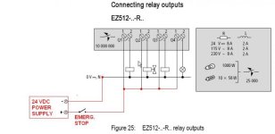
If you must use the Emergency Stop switch, then wire it up something like this (modified Fig. 25 from Page 52 of the EZ User Manual) so that it will kill the +24 volt line to all of your EZ outputs. Generally it is not necessary to kill the power to 24 VDC PLC Inputs, but if that is required for safety reasons, then use the other contact of your E-Stop switch for that purpose.

Notice the table on the right. It shows that for a 24 VDC power supply, the EZ output relays can handle up to a 8 Amp resistive load, but only a 2 Amp inductive load (such as a solenoid or motor starter coil). Check your output devices (spray solenoid mainly) to make sure they are within the limit. Otherwise you will have to add interposing relays between the EZ outputs and your devices.

You will need a few additional rungs if the timer value needs to change from Speed 1 to Speed 2. I recommend adding a 2nd timer that is activated when Speed 2 is on. Then the first T1 can be activated by Speed 1. Do you know the speeds (you will have to know them in order to program the VFD) and the times for spraying at each speed?

EASY Output Wiring.jpg
 
Last edited:
Lancie1 I'm not aware of the speeds as of yet. It's going to be a trial and error when the system is up and operating. And I totally agree with the second timer while speed.2 is on as well. Being that the item is going to be of different size. Adding that second rung how would that look on a ladder? Similar to the first I imagine? Just tied off of q3?
 
I think now that your program should look about like the attached picture. The changes are:

1. Elimination of the Power ON input (I can't see a definite need for that but it is optional);

2. Added rung comments to each rung;

3. Split the timer rung into 2 rungs due to the limitation of only 3 inputs per rung on the EZ;

4. Added Timer T02 to Rung 007;

5. Added a new rung 010 for the Q04 Spray Jet Solenoid, with both timers now able to control the ON time of Q04;

6. Added Rung 012 for the new M02 "Stop Continuous Loop" internal relay. Use Input I07 (I07 ON = Continuous Mode Stopped, I07 OFF = Continuous Mode where Photoeye 2 does not stop the conveyor).

Conveyor Spray Jet- Freakafter8.jpg
 
Last edited:
okay that looks about it I'm going to try that program.

one more thing do you think I can use the 24 volt power supply that supplies the PLC input voltage for running the spray jet coil and the switches or buttons or should I get an independent power supply?
 

Similar Topics

Hello, I’m new to this forum and if I’m posting incorrectly let me know. I’ve been having an issue I can’t seem to figure out. I’m sure it’s...
Replies
1
Views
126
Hi everyone: we have Baumuller AC drive BM4463 300A 160KW, it drives Baumuller AC motor DST2-315BO54W-020-5-A (90KW;RPM 200; 365V; 215A;83Hz)...
Replies
2
Views
364
Hello everybody, Since my experience is mainly with AB ladder I am having little bit of a problem with EasySoft.. Does anyone knows is there a...
Replies
4
Views
837
Good morning, i have a problem with panelmate 5000 pp. unfortunately I pressed the 3rd and 5th keys while booting the Panel. Now , the alternate...
Replies
0
Views
520
Hey everyone! So I'm trying to get different data from my Eaton DG1 VFD to my studio project. So far my research has led me to something called...
Replies
10
Views
1,565
Back
Top Bottom